
Method and apparatus for managing an energy consuming load

a technology for managing energy consumption and load, applied in the integration of power network operation systems, process and machine control, instruments, etc., can solve problems such as the increase in complexity of the internal organization of a system, and achieve the effect of reducing energy consumption

Active Publication Date: 2008-01-17
ENCYCLE CORP
View PDF21 Cites 315 Cited by
  • Summary
  • Abstract
  • Description
  • Claims
  • Application Information

AI Technical Summary

Benefits of technology

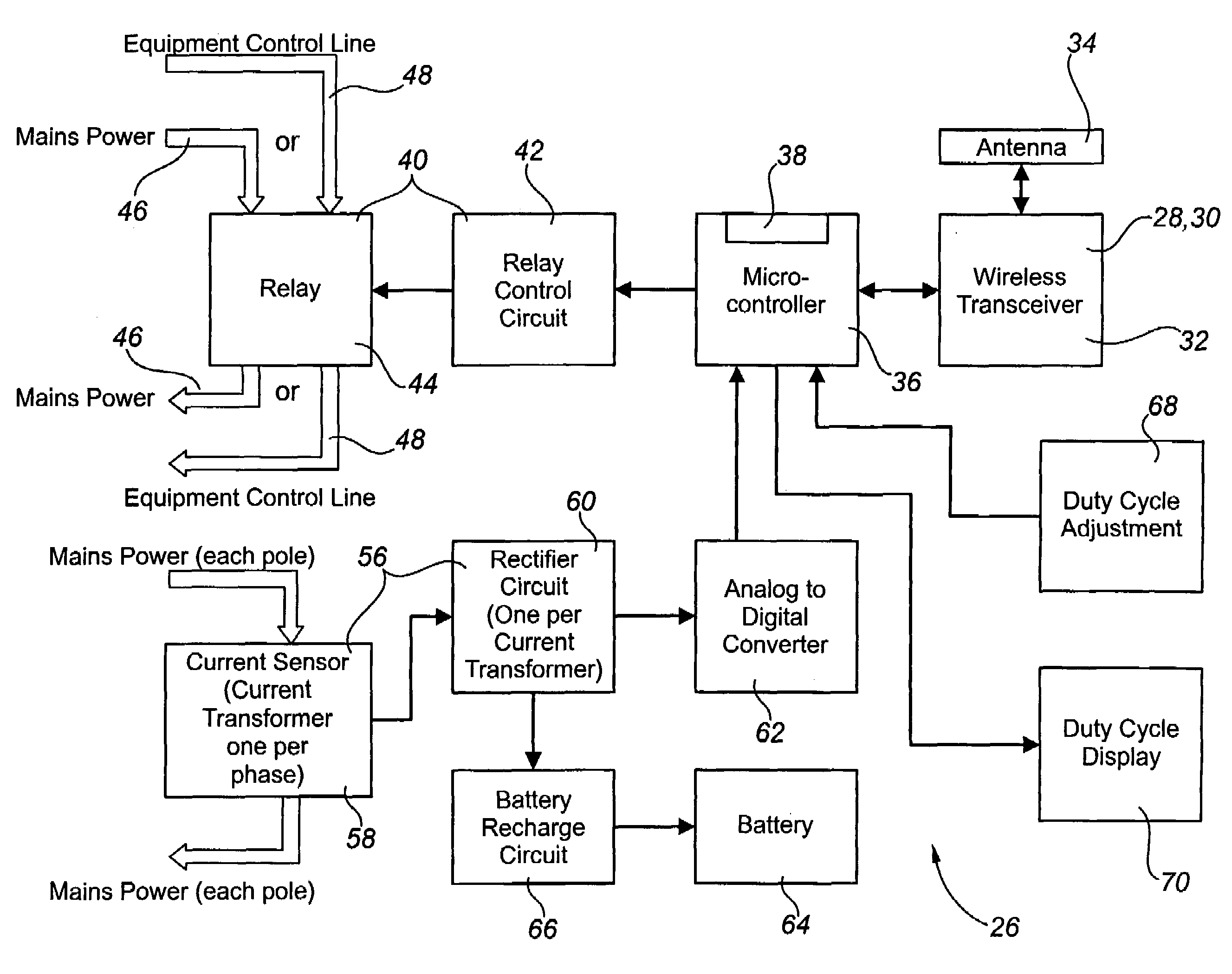
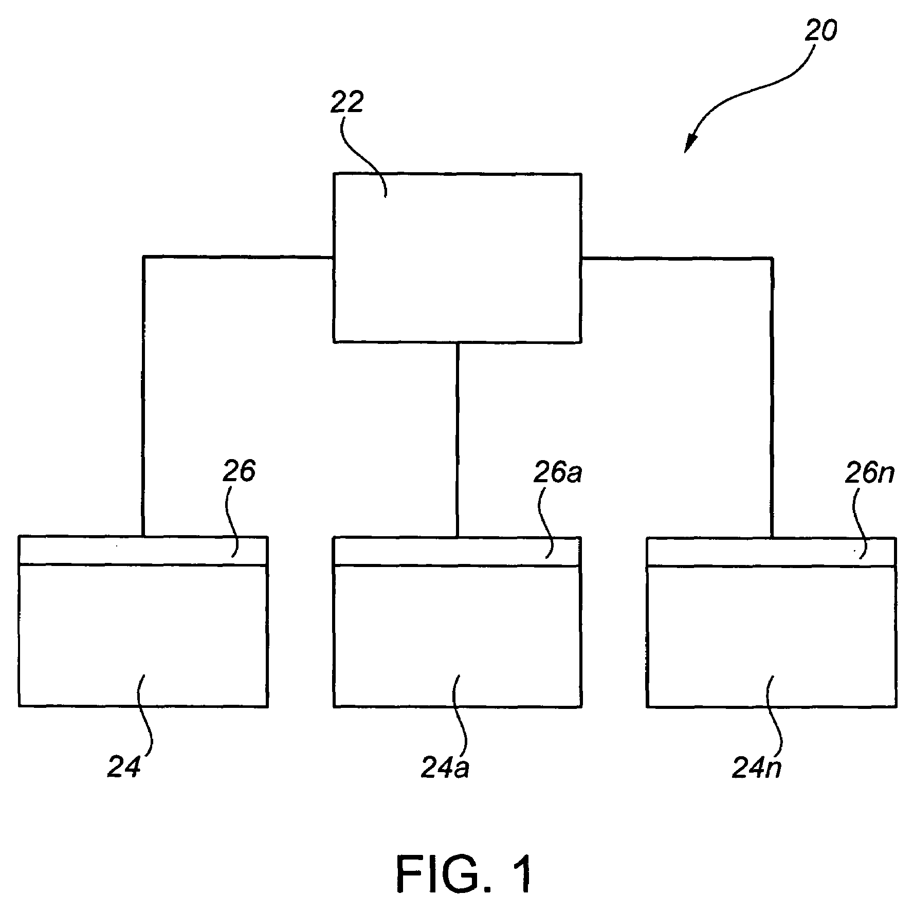
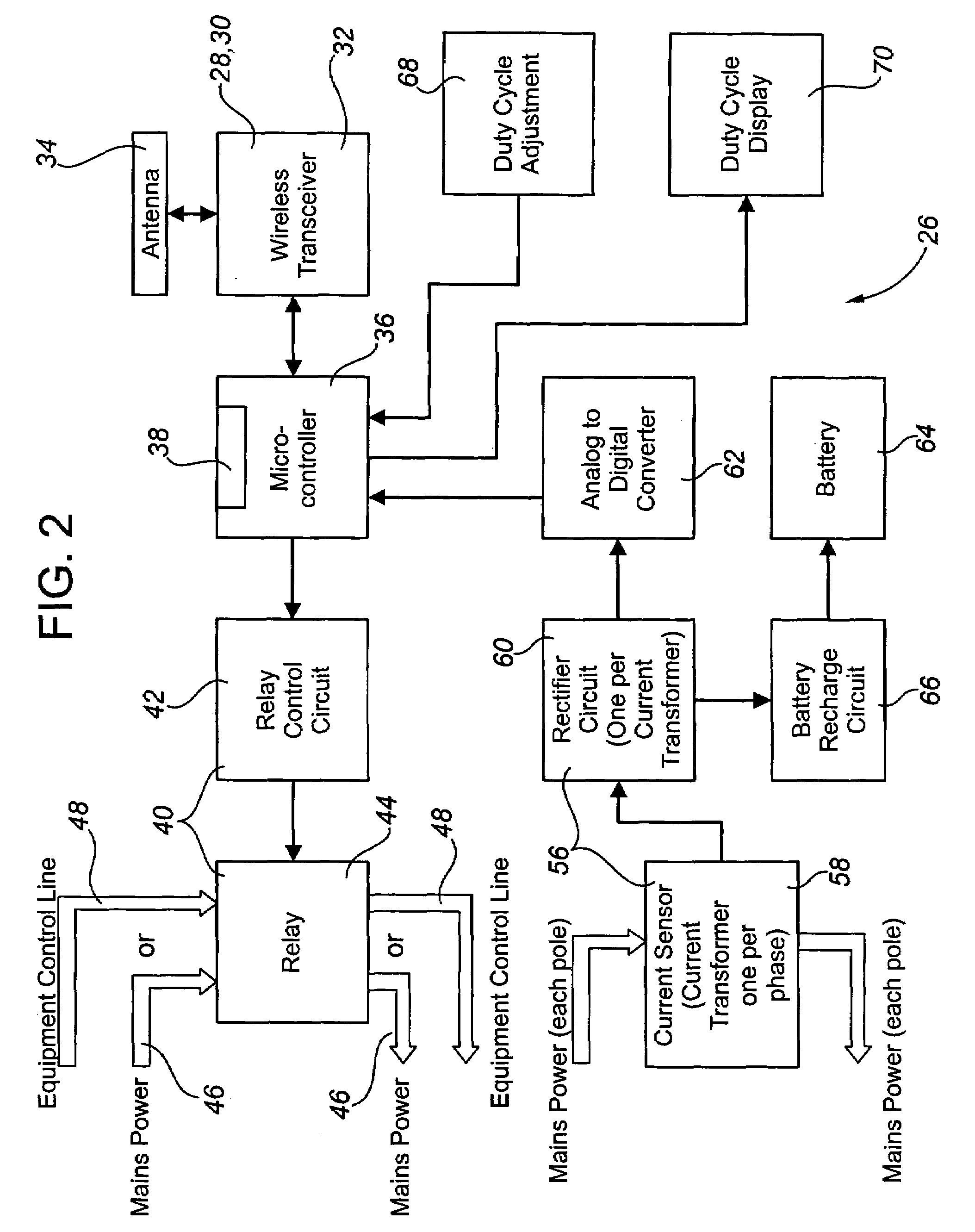
[0040]The apparatus of the invention may also include a processor which facilitates generating information about an energy consuming load in a group of energy consuming loads, compiling information about the group of energy consuming loads and making a decision relating to the management of the load using the compiled information. The computer readable medium of the invention may provide computer readable instructions for directing the processor.
[0072]A duty cycle may also be an assigned duty cycle which may be less than or greater than the natural duty cycle of the load. An assigned duty cycle may, for example, be assigned to be less than the natural duty cycle in order to reduce energy consumption, and may be assigned to be greater than the natural duty cycle in order to provide increased assurance that the load will satisfy its assigned objectives.

Problems solved by technology

Escalating energy costs and infrastructure costs have made managing both energy supply and energy consumption a critical issue which is important to both suppliers of energy and consumers of energy.
Self organization is a process in which the internal organization of a system increases in complexity without guidance or management from an outside source.
A multi-agent system is a system composed of a group of agents which interact according to defined rules to achieve functionality that would be difficult or impossible to achieve by the agents acting individually.

Method used


Image

  • Method and apparatus for managing an energy consuming load
  • Method and apparatus for managing an energy consuming load
  • Method and apparatus for managing an energy consuming load

Examples


example

[0248]The following example serves more fully to illustrate the invention. In particular, FIG. 9 provides the results of an example of the performance of the algorithms or sets of instructions provided in the flow charts of FIGS. 5 through 8b by the apparatus (26). For the example, the period is comprised of 12 segments and the group of loads is comprised of three loads, being the load (24) and two other loads (24a, 24b), having the following characteristics:

ICSEIMAXWattsnSNWattsrDC %Contribution tosegmentsMaxDutysystemin PeriodnSNLoad #LoadCycleequilibriumneededrounded150055%2756.672100040%4004.853150030%4503.64ITSE1125

[0249]The results are set out in FIG. 9 for each of the three loads and for each of the twelve segments of the period. As shown in FIG. 9, the resulting average load for the period is 1208.333 Watts, while the peak load or peak energy demand for the period is 1500 Watts.


PUM


Abstract

A method for managing an energy consuming load in a group of energy consuming loads and a method for managing the group of energy consuming loads. The method includes generating sets of load state data from the loads, making enablement state decisions for one or more loads independently of the other loads using the sets of load state data, and implementing the enablement state decisions. An apparatus for managing an energy consuming load in a group of energy consuming loads, including a transmitter for transmitting a set of load state data generated from the load, a receiver for. receiving sets of load state data from other loads, a processor for processing the sets of load state data to make an enablement state decision for the load, and a controller for implementing the enablement state decision.

Description

TECHNICAL FIELD[0001]A method and apparatus for managing a group of energy consuming loads and for managing an energy consuming load in a group of energy consuming loads.BACKGROUND OF THE INVENTION[0002]Energy is provided by suppliers to consumers in many forms and from many sources. Typical forms and sources of energy include electricity, natural gas, coal, oil, atomic energy etc.[0003]Escalating energy costs and infrastructure costs have made managing both energy supply and energy consumption a critical issue which is important to both suppliers of energy and consumers of energy.[0004]From a supplier's perspective, both the energy consumption of consumers and the energy demand by consumers must be accommodated by the energy infrastructure. Energy consumption is the total amount of energy which is consumed over a time period, while energy demand is the rate at which the energy is consumed. Peak energy demand is the maximum rate at which energy is consumed. Energy consumption over a...

Claims


Application Information

Patent Timeline
IPC IPC(8): H02J3/14
CPCH02J3/14Y04S20/222Y02B70/3225H02J13/0075H02J13/00026H02J13/00034H02J2310/60H02J3/144H02J2310/54Y04S40/126Y02E60/00
Inventor KULYK, ROMANKERBEL, MARK
Owner ENCYCLE CORP
Learn More