Glass run integral molding and door frame structure

a technology of integral molding and door frame, which is applied in the direction of doors, transportation and packaging, mechanical equipment, etc., can solve the problem that the glass run integral molding is more likely to be undetectedly removed from the door frame, and achieve the effect of reducing the weight of the door fram

Inactive Publication Date: 2013-08-29
AISIN SEIKI KK
View PDF12 Cites 16 Cited by
  • Summary
  • Abstract
  • Description
  • Claims
  • Application Information

AI Technical Summary

Benefits of technology

[0014]In this case, the flange portion of the door frame has the double-layered structure of the thin steel plate. Therefore, as compared with the case where the flange portion has the triple-layered structure of the thin steel plate, the weight of the door frame can be reduced. Moreover, an operation of firmly fixing a lower end portion of the door frame to the door panel (for example, a door inner panel) at the flange portion (for example, an operation of spot-welding three layers of the steel plate, including the door inner panel and the thin steel plate having the double-layered structure) can be easily performed as compared with an operation performed in the case where the flange portion has the triple-layered structure of the thin steel plate (for example, an operation of spot-welding four layers of the steel plate, including the door inner panel and the thin steel plate having the triple-layered structure).

Problems solved by technology

As a result, the glass run integral molding is more likely to be undesirably removed from the door frame.

Method used


Image

  • Glass run integral molding and door frame structure
  • Glass run integral molding and door frame structure
  • Glass run integral molding and door frame structure

Examples


first embodiment

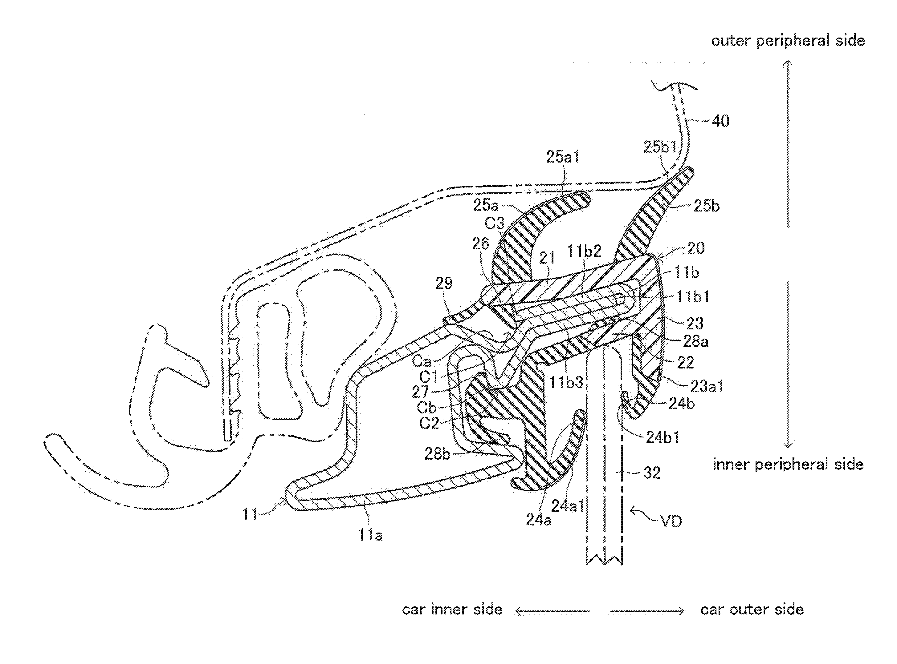
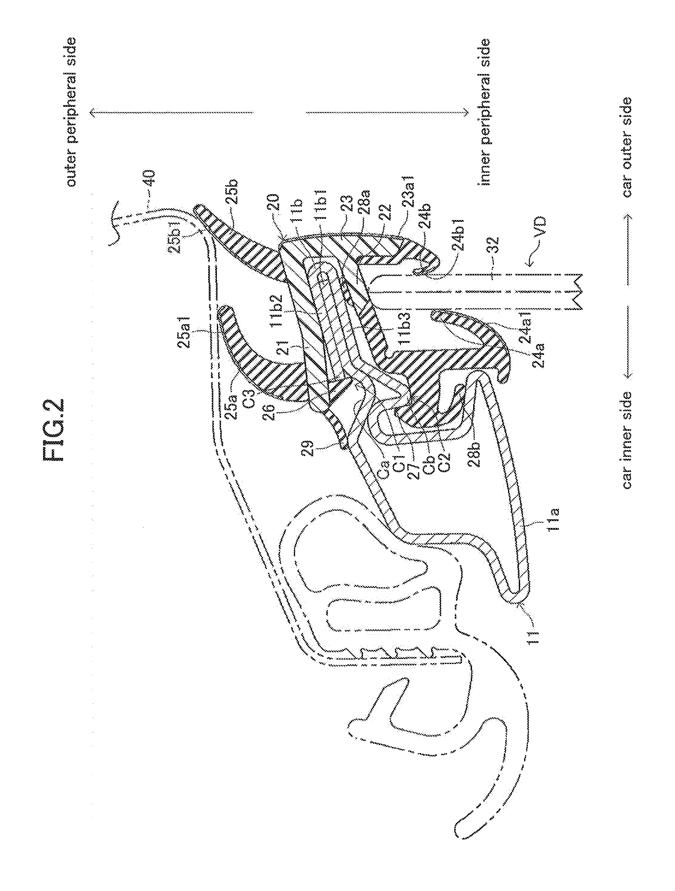
[0033]According to the glass run integral molding 20 of this embodiment (first embodiment), which is configured as described above, the outer peripheral-side engagement portion 26 is configured to come into elastic engagement with the first engagement portion C1 formed on the outer peripheral side of the upper part 11 of the door frame 10 from the outer peripheral side and the inner peripheral-side engagement portion 27 is configured to come into elastic engagement with the second engagement portion C2 formed on the inner peripheral side of the upper part 11 from the inner peripheral side. Specifically, a direction in which the outer peripheral-side engagement portion 26 comes into engagement with the first engagement portion C1 and a direction in which the inner peripheral-side engagement portion 27 comes into engagement with the second engagement portion C2 are opposite to each other, and therefore are opposed to each other.

[0034]Thus, when the door glass 32 is closed and the glas...

third embodiment

[0044]In the third embodiment illustrated in FIG. 7, a glass run integral molding 120 to be assembled to the upper part 111 is configured in the same manner as that of the glass run integral molding 20 illustrated in FIG. 3. Specifically, the glass run integral molding 120 includes an outer peripheral-side side wall portion 121 and an inner peripheral-side side wall portion 122, a car outer-side side wall portion 123, a pair of glass run portions 124a and 124b, and a pair of body seal lip portions 125a and 125b in an integrated manner. The outer peripheral-side side wall portion 121 and the inner peripheral-side side wall portion 122 sandwich the flange portion 111b. The car outer-side side wall portion 123 connects a car outer-side end portion of the outer peripheral-side side wall portion 121 and that of the inner peripheral-side side wall portion 122 to each other and extends along a door glass surface. The pair of glass run portions 124a and 124b are formed so as to extend respe...

sixth embodiment

[0050]In the sixth embodiment illustrated in FIG. 10, an upper part 211 of the door frame is formed by bending a thin steel plate, and includes a hollow base portion 211a and a flange portion 211b. The flange portion 211b has a double-layered structure in which an outer peripheral-side plate 211b1 and an inner peripheral-side plate 211b2 are laminated and are spot-welded at an overlapping portion. Since the flange portion 211b has the double-layered structure of the thin steel plate, weight and cost can be reduced as compared with the case of the triple-layered structure. Moreover, an end portion of the flange portion 211b is easy to spot-weld to a door inner panel (not shown) of the vehicle door VD. The portion welded to the door inner panel forms the triple-layered structure of the thin steel plate. A car inner-side portion of the outer peripheral-side plate 211b1 of the flange portion 211b is protruded to the car inner side and the car outer side to form a convex portion Fa and a...


PUM


Abstract

To prevent easy removal of a glass run integral molding from a door frame, provided is a glass run integral molding to be assembled to an upper part of a door frame surrounding a window opening of a vehicle door. The glass run integral molding includes an outer peripheral-side side wall portion and an inner peripheral-side side wall portion for sandwiching a flange portion of the upper part, a car outer-side side wall portion for connecting a car outer-side end portion of the outer peripheral-side side wail portion and that of the inner peripheral-side side wall portion to each other and extending along a door glass surface, glass run portions for sealing a peripheral edge of a door glass, and body seal lip portions for sealing a clearance between the vehicle door and a vehicle body. The glass run integral molding also includes an outer peripheral-side engagement portion for coming into elastic engagement with a first engagement portion formed on an outer peripheral side of the upper part from the outer peripheral side and an inner peripheral-side engagement portion for coming into elastic engagement with a second engagement portion formed on an inner peripheral side of the upper part from the inner peripheral side.

Description

TECHNICAL FIELD[0001]The present invention relates to a glass run integral molding adapted to be assembled to a door frame surrounding a window opening of a vehicle door and a door frame structure including the glass run integral molding and the door frame.RELATED ART[0002]A glass run integral molding (a molding with which a glass run is integrated) to be assembled to a door frame surrounding a window opening of a vehicle door is described in, for example, JP 2005-153581 A. The glass run integral molding, which is described in JP 2005-153581 A, includes an outer peripheral-side side wall portion and an inner peripheral-side side wall portion, a car outer-side side wall portion, a glass run portion, and a body seal lip portion in an integrated manner. The outer peripheral-side side wall portion and the inner peripheral-side side wall portion sandwich a flange portion formed on an upper part of a door frame. The car outer-side side wall portion connects a car outer-side end portion of...

Claims


Application Information

Patent Timeline
Patent Type & Authority Applications(United States)
IPC IPC(8): B60J10/04B60J10/08
CPCB60J10/088B60J10/08B60J10/04B60J10/88B60J10/74B60J10/80B60J10/18B60J5/0402
Inventor TAKEUCHI, KATSUHIKOYAMASAKI, HIROAKISATO, EISUKE
Owner AISIN SEIKI KK
Why Eureka
Try Eureka