Wireless charging device, terminal, and method for wireless charging

a wireless charging and terminal technology, applied in the direction of electric vehicles, transportation and packaging, transmission, etc., can solve the problems of reducing the efficiency of charging, affecting the charging efficiency of the primary coil, and affecting the charging efficiency of the secondary coil, so as to achieve the effect of increasing the charging efficiency

Inactive Publication Date: 2013-08-29
PANTECH CO LTD
View PDF1 Cites 54 Cited by
  • Summary
  • Abstract
  • Description
  • Claims
  • Application Information

AI Technical Summary

Benefits of technology

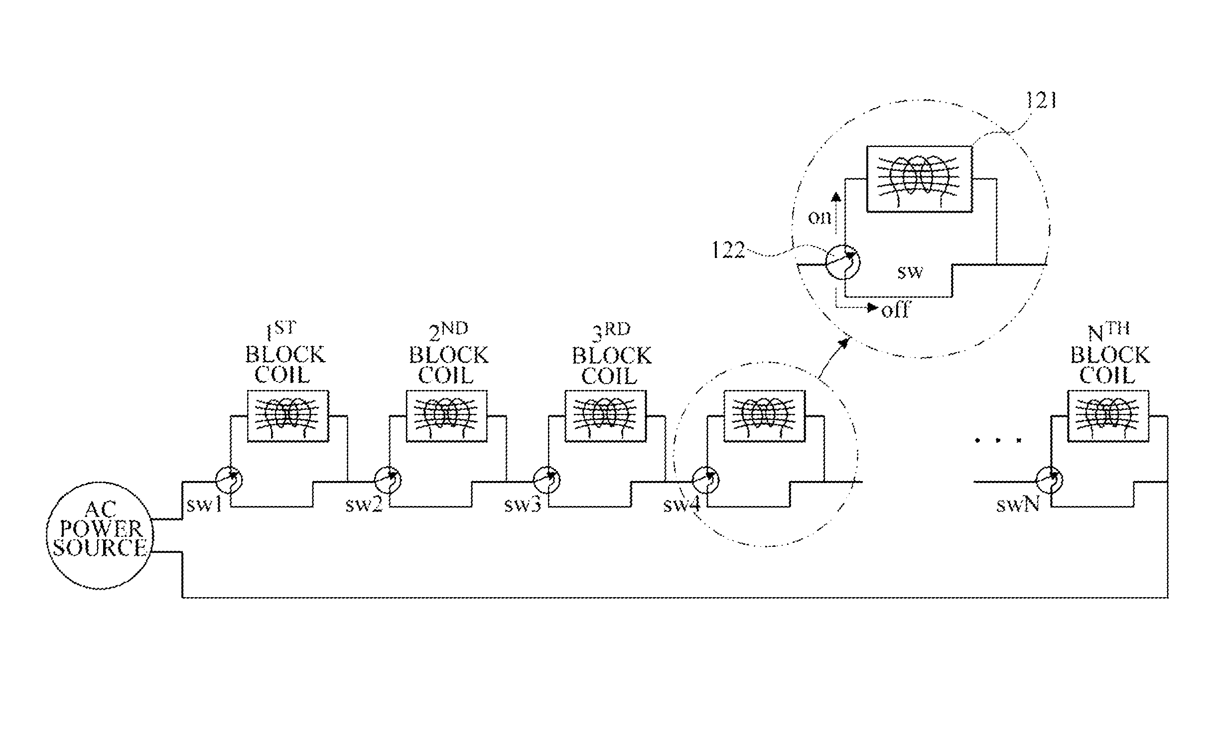
[0018]Exemplary embodiments of the present invention provide a non-contact charging device, terminal, and method for non-contact charging. The matching between a primary coil and a secondary coil may be adjusted by switching primary coil blocks to provide an increased charging efficiency.

Problems solved by technology

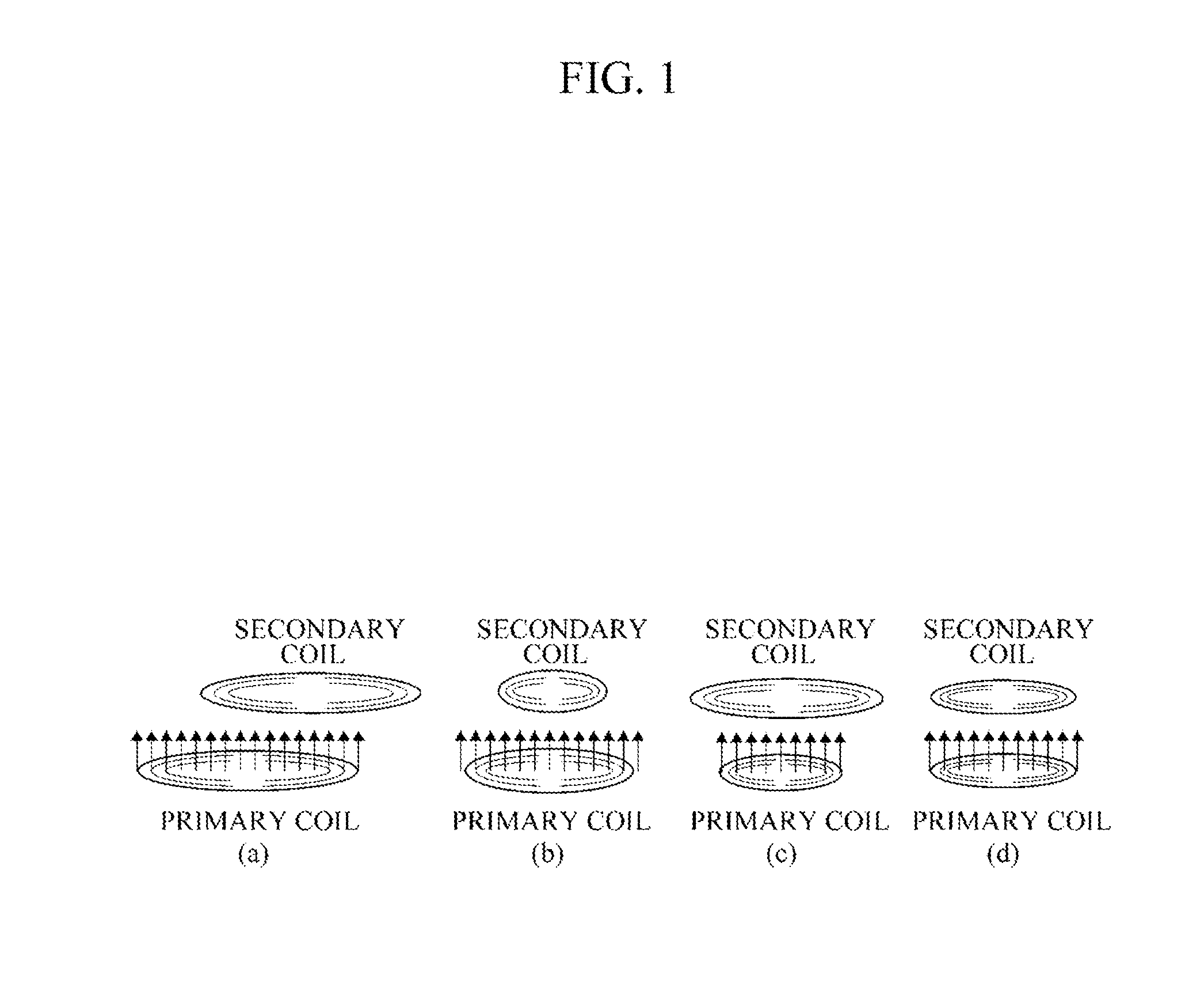
Accordingly, part of the power transmitted by the primary coil may not be conveyed to the secondary coil, and the efficiency of charging may decrease.
Referring to FIG. 1(c), if the area of a primary coil is smaller than the area of a secondary coil, the secondary coil may receive all the magnetic flux variation transmitted by the is primary coil, but the received magnetic flux variation may be insufficient due to the small area of the primary coil.
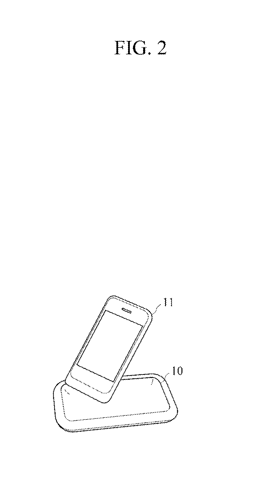
However, the non-contact charging device 10 may not charge other terminals having different secondary coils efficiently.
In addition, even the terminal 11 may not be properly charged unless the charged terminal 11 is properly located on the non-contact charging device 10.
However, since various terminals have different sizes and various secondary coil capacities, it may be difficult to design a non-contact charging device that is fit and efficient for all types of terminals.
Also, in a method of searching for a matching primary coil for a secondary coil with the use of an ambient light sensor, a proximity sensor, etc., the primary coil may be placed at a wrong place so that charging may fail.
Also, the efficiency of charging may decrease, and the manufacturing cost of a non-contact charging device may increase due to the use of the sensors and the driving motor.

Method used


Image

  • Wireless charging device, terminal, and method for wireless charging
  • Wireless charging device, terminal, and method for wireless charging
  • Wireless charging device, terminal, and method for wireless charging

Examples


Embodiment Construction

[0043]The invention is described more fully hereinafter with reference to the accompanying drawings, in which exemplary embodiments of the invention are shown. This invention may, however, be embodied in many different forms and should not be construed as limited to the exemplary embodiments set forth herein. Rather, these exemplary embodiments are provided so that this disclosure is thorough, and will fully convey the scope of the invention to those skilled in the art. It will be understood that for the purposes of this disclosure, “at least one of X, Y, and Z” can be construed as X only, Y only, Z only, or any combination of two or more items X, Y, and Z (e.g., XYZ, XZ, XYY, YZ, ZZ). Throughout the drawings and the detailed description, unless otherwise described, the same drawing reference numerals are understood to refer to the same elements, features, and structures. The relative size and depiction of these elements may be exaggerated for clarity.

[0044]It will be understood tha...


PUM


Abstract

A method for operating a wireless charging device includes detecting a chargeable terminal, detecting a valid block coil according to information transmitted from the chargeable terminal, switching on the valid block coil, and controlling a current supply to the valid block coil. A terminal includes a receiving coil configured to induce a current in response to receipt of wireless power, an induced voltage detection unit to measure an induced voltage generated by the induced current, and to generate induced voltage information, and a communication unit to transmit the induced voltage information to a wireless charging device.

Description

CROSS-REFERENCE TO RELATED APPLICATION[0001]This application claims priority from and the benefit under 35 U.S.C. §119(a) of Korean Patent Application No. 10-2012-0021399, filed on Feb. 29, 2012, which is incorporated herein by reference for all purposes as if fully set forth herein.BACKGROUND[0002]1. Field[0003]The following description relates to a non-contact charging device, terminal, and method for non-contact charging.[0004]2. Discussion of the Background[0005]Various Information Technology (IT) devices, such as mobile communication terminals (for example, smartphones or Personal Digital Assistants (PDAs)), notebook is computers, etc., have emerged and become widespread. Such devices include portable devices and are equipped with batteries for power supply. Conventionally, a device equipped with a battery may be charged by detaching the battery from the device and inserting the battery into a battery charger or connecting the device with a battery charger while keeping the bat...

Claims


Application Information

Patent Timeline
Patent Type & Authority Applications(United States)
IPC IPC(8): H02J7/00
CPCH02J7/0042H02J7/0052H02J7/025H02J7/0044H02J5/005H02J50/402H02J50/80H02J50/005H02J50/10H04B5/0093H04B5/0037H02J7/0036
Inventor KIM, JAE-KI
Owner PANTECH CO LTD
Why Eureka
Try Eureka