High-gain wideband antenna apparatus

a wideband antenna and high-gain technology, applied in the direction of antenna equipment with additional functions, antenna details, antennas, etc., can solve the problems of narrow bandwidth and inability to easily apply for transmission and reception of wideband signals

Inactive Publication Date: 2013-08-29
ELECTRONICS & TELECOMM RES INST
View PDF5 Cites 35 Cited by
  • Summary
  • Abstract
  • Description
  • Claims
  • Application Information

AI Technical Summary

Benefits of technology

[0019]An embodiment of the present invention relates to a high-gain wideband antenna apparatus, including: a cylindrical cover configured to include conductor patterns formed in a specific shape; a plurality of feeding antennas c

Problems solved by technology

The Fabry-Perot resonator type antenna can improve the gain of the antenna, but has a too narrow

Method used


Image

  • High-gain wideband antenna apparatus
  • High-gain wideband antenna apparatus
  • High-gain wideband antenna apparatus

Examples


first embodiment

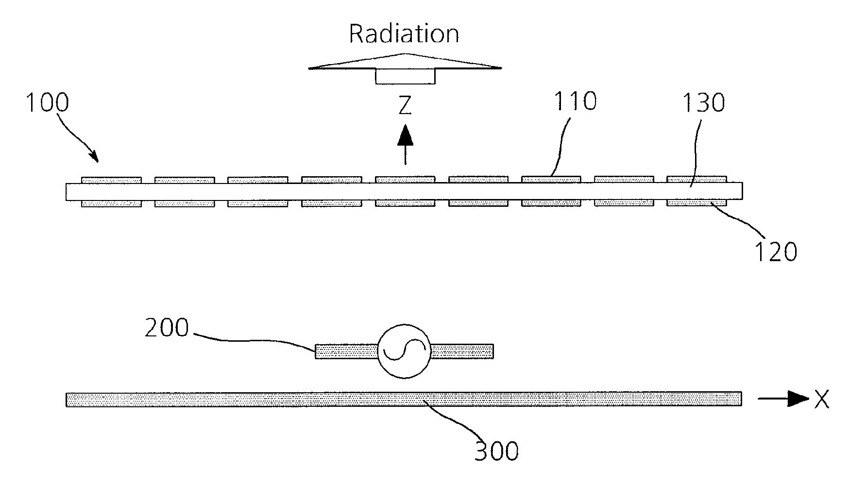
[0035]FIG. 1 is a diagram illustrating a structure of a high-gain wideband antenna apparatus in accordance with the present invention.

[0036]As illustrated in FIG. 1, a high-gain wideband antenna apparatus in accordance with a first embodiment of the present invention includes a cover 100, a feeding antenna 200, and a ground surface 300.

[0037]In this case, the high-gain wideband antenna apparatus in accordance with the embodiment of the present invention may further include metal wall surfaces 400 that are disposed at sides of the feeding antenna 200 based on a radiation direction of a signal so as to improve a front back ration (FBF) of an antenna.

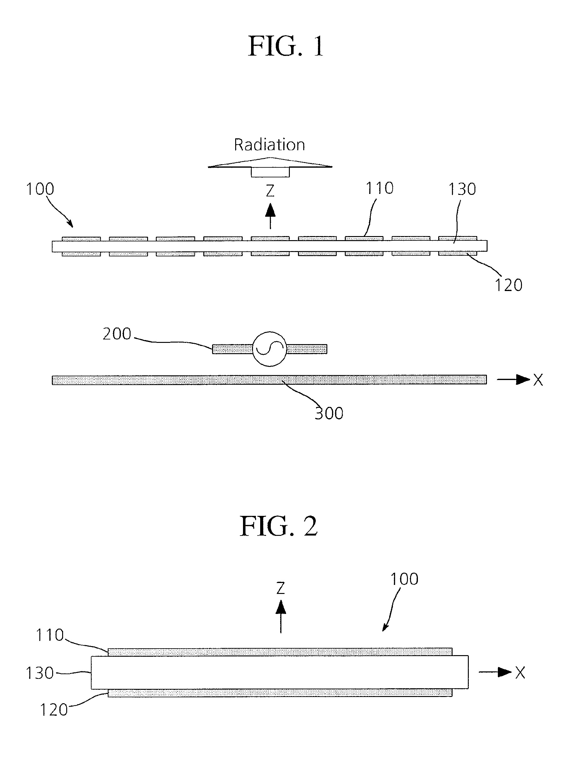
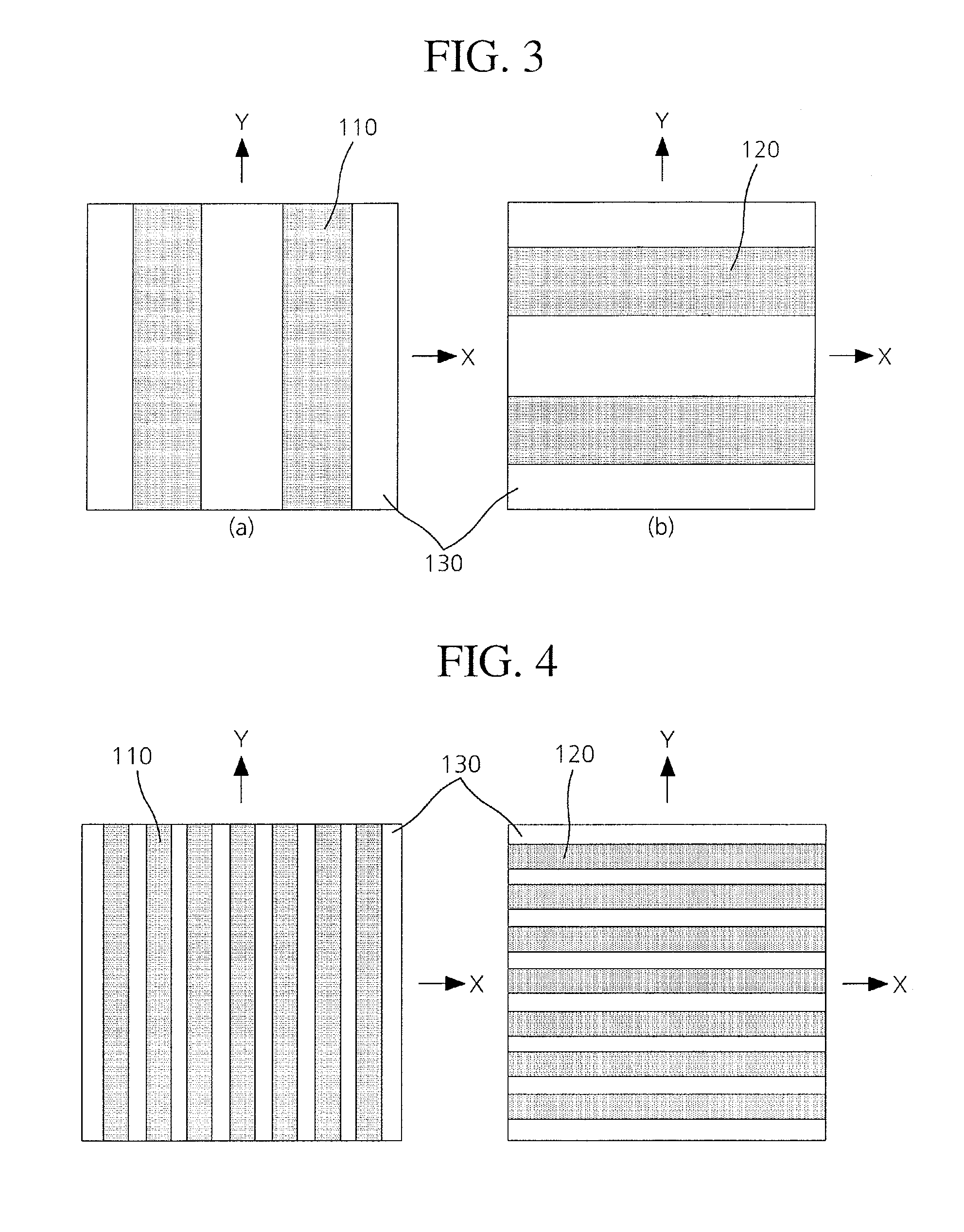
[0038]FIG. 2 is a side view illustrating a cover of the high-gain wideband antenna apparatus in accordance with the first embodiment of the present invention and FIG. 3A and 3B are exemplified diagrams of unit cells configuring conductor patterns on both surfaces of the cover of the high-gain wideband antenna apparatus in accordance with t...

second embodiment

[0059]FIG. 8 is a diagram illustrating a structure of a high-gain wideband antenna apparatus in accordance with the present invention.

[0060]The first embodiment of the present invention as described above describes, for example, when the high-gain wideband antenna apparatus includes the ground surface 300 disposed on the back surface of the feeding antenna 200 based on the radiation direction of the signal.

[0061]However, the high-gain wideband antenna apparatus in accordance with the embodiment of the present invention may be implemented to include the extra cover 100 instead of the ground surface 300.

[0062]That is, the high-gain wideband antenna apparatus in accordance with the embodiment of the present invention may include a plurality of covers 100 that includes the conductor patterns 110 and 120 formed on the top and bottom surfaces of the dielectric substrate 130 and the feeding antenna 200 that is disposed between the plurality of covers 100 to radiate the signal toward the pl...

third embodiment

[0064]FIG. 9 is a diagram illustrating a structure of a high-gain wideband antenna apparatus in accordance with the present invention, FIG. 10 is a graph illustrating a change in an antenna gain when metal wall surfaces are mounted as illustrated in FIG. 9, and FIG. 11 is a graph illustrating a change in an antenna front back ratio when the metal wall surfaces are mounted as illustrated in FIG. 9.

[0065]Unlike the first and second embodiments as described above, the high-gain wideband antennal apparatus in accordance with the present invention may further include metal surfaces 400 that are disposed at the sides of the feeding antenna 200 based on the radiation direction of the signal as illustrated in FIG. 9.

[0066]Referring to FIG. 10, it can be appreciated that the case in which the conductor patterns 110 and 120 of the cover 100 are uniformly arranged exhibits more excellent wideband characteristics than the case in which the conductor patterns 110 and 120 of the cover 100 are non...


PUM


Abstract

Disclosed is a high-gain wideband antenna apparatus. The high-gain wideband antenna apparatus, includes: a feeding antenna configured to radiate a signal; a cover configured to be disposed on a front surface of the feeding antenna based on a radiation direction of the signal and including a conductor pattern formed in a specific shape; and a ground surface configured to be disposed on the feeding antenna based on the radiation direction of the signal. By this configuration, the conductor patterns are approximately configured on both surfaces of a dielectric material to control a phase of a reflection coefficient in a specific frequency band, thereby increasing a gain and a bandwidth of an antenna and metal surfaces are additionally mounted on sides of a feeding antenna, thereby improving a front back ratio of the antenna.

Description

CROSS-REFERENCES TO RELATED APPLICATIONS[0001]The present application claims priority under 35 U.S.C 119(a) to Korean Application No. 10-2012-0019956, filed on Feb. 27, 2012, in the Korean Intellectual Property Office, which is incorporated herein by reference in its entirety set forth in full.BACKGROUND[0002]Exemplary embodiments of the present invention relates to a high-gain wideband antenna apparatus, and more particularly, to a high-gain wideband antenna apparatus capable of controlling a phase and a magnitude of a reflection coefficient by including a cover in which conductor patterns having a specific shape are arranged on both surfaces of a dielectric material.[0003]Generally, an antenna, which is an essential apparatus for transmitting and receiving a signal in a wireless communication system, is resonated with an electromagnetic wave of a specific frequency to transmit and receive an electromagnetic signal of a corresponding frequency.[0004]Recently, with the rapid develop...

Claims


Application Information

Patent Timeline
IPC IPC(8): H01Q15/02
CPCH01Q15/02H01Q15/0053H01Q15/0013H01Q1/425H01Q1/38H01Q1/46H01Q5/00
Inventor JU, JEONGHO
Owner ELECTRONICS & TELECOMM RES INST
Why Eureka
Try Eureka