Thin display device

a display device and thin technology, applied in the field of thin display devices, can solve the problems of increased cost, loss of fresnel, increased number, etc., and achieve the effects of improving light reflection efficiency, large refractive index, and improving non-uniformity of luminan

Inactive Publication Date: 2013-08-29
FUNAI ELECTRIC CO LTD
View PDF4 Cites 5 Cited by
  • Summary
  • Abstract
  • Description
  • Claims
  • Application Information

AI Technical Summary

Benefits of technology

[0012]As a result of a material with a large refractive index being used in the light guide plate, the refractive index along the parallel direction of the optically anisotropic member disposed on the plane of incidence of the light guide plate is a relatively large value. Therefore, it is possible to maintain “as is” an advantage that a large angle of diffusion of the light along the parallel direction of the light guide plate can be obtained, so that the number of the light sources that are required can be small, which is economical. Furthermore, the refractive index along the vertical direction of the optically anisotropic member is small, so the angle of reflection of the light with respect to the front surface and rear surface of the light guide plate becomes large. Therefore, leaking of light from the front surface of the light guide plate is prevented, so the light reflection efficiency is improved, thus making it possible to improve non-uniformity of luminance to a great extent.
[0013]In essence, with the use of the optically anisotropic member, the advantage of the light guide plate having a large refractive index is utilized “as is,” and the drawbacks thereof are eliminated.
[0014]In addition, because there is preferably no air space between the light-emitting diode chips and the optically anisotropic member, light emitted from the light-emitting diode chips passes through the optically anisotropic member “as is” and is diffused within the light guide plate, so it is possible to eliminate the occurrence of Fresnel loss seen in the past and to significantly ameliorate the light entry efficiency.

Problems solved by technology

However, the angle of diffusion α of the light a along the parallel direction Y becomes narrow as shown in FIG. 4D, which creates a need to increase the number of the light sources 5 corresponding to the degree of narrowing, and this increases the cost.
Therefore, the light a emitted from the light sources 5 is reflected by the plane of incidence 4a, causing Fresnel loss to occur, so there is a disadvantage in that light entry efficiency is worsened.

Method used


Image

  • Thin display device
  • Thin display device
  • Thin display device

Examples


Embodiment Construction

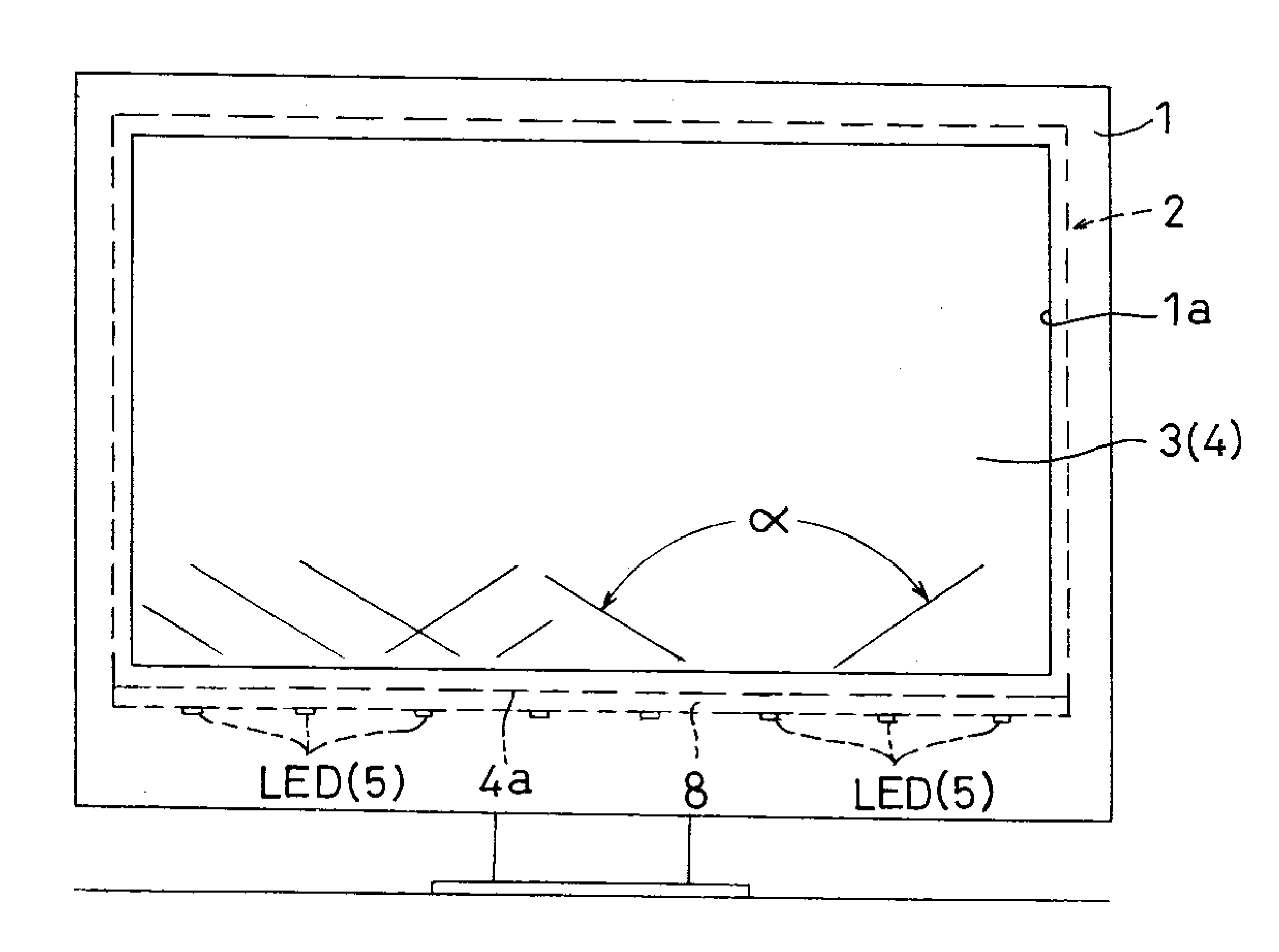
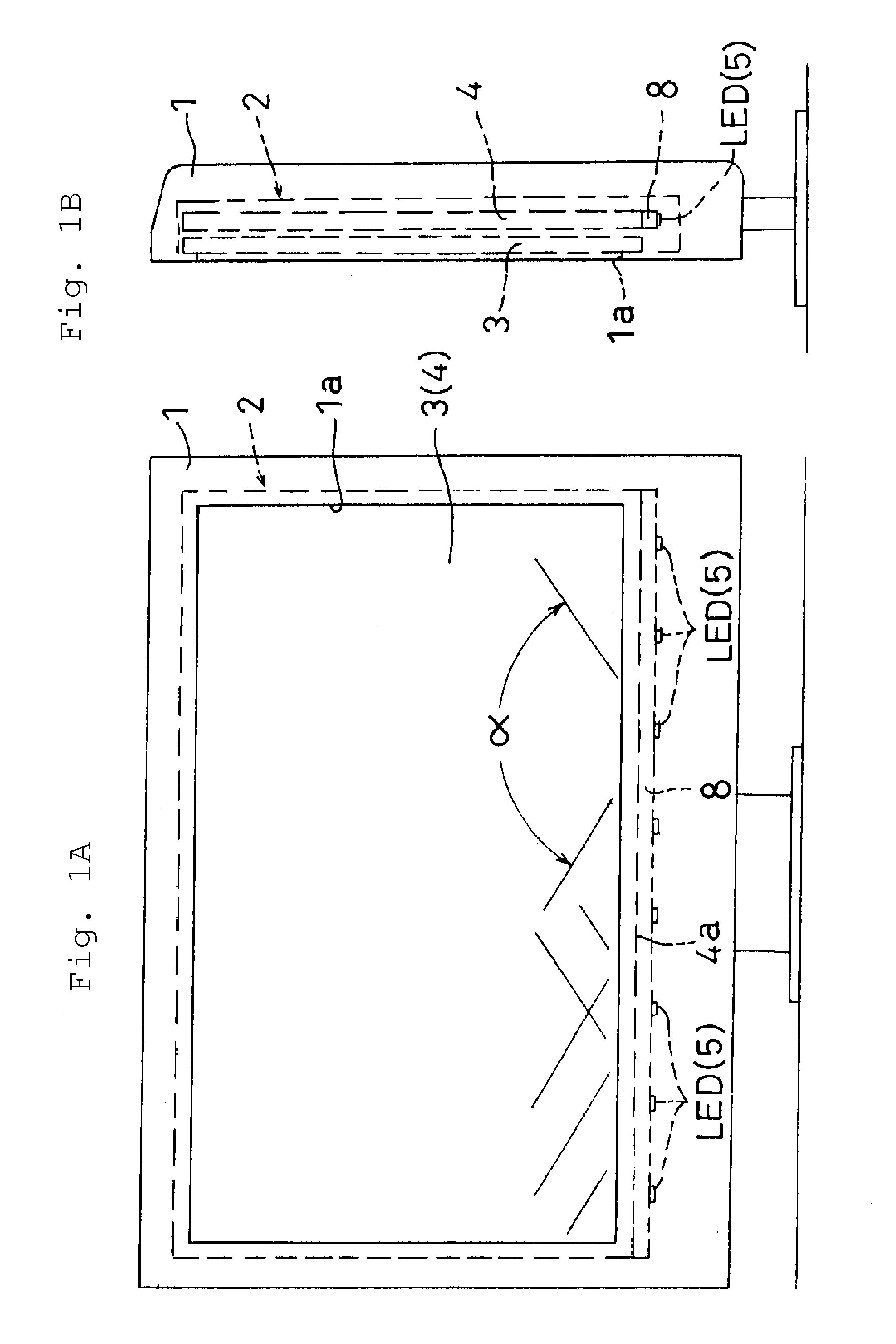
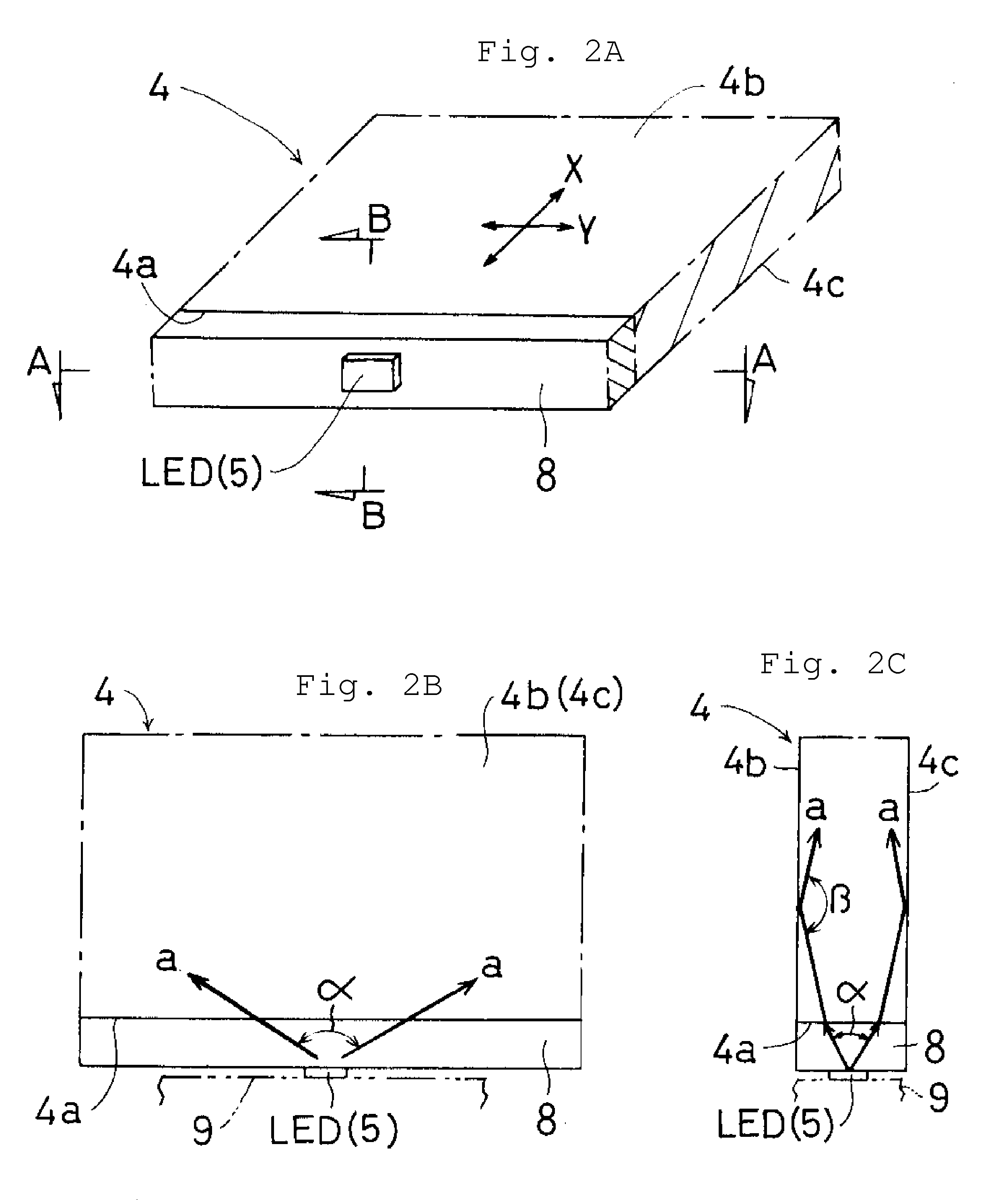
[0020]FIGS. 1A-2C show a thin display device according to a preferred embodiment of the present invention, which preferably is a liquid crystal television. In the thin display device according to the present preferred embodiment, an optically anisotropic member 8 is disposed on a plane of incidence 4a of a light guide plate 4, and light-emitting diode chips LED are used as the light source 5. Note that 9 is a substrate that supports the light-emitting diode chips LED. The configuration other than described above is almost the same as the configuration shown in FIGS. 3A-4E, so the same symbols are assigned to the same elements, and the description thereof will be omitted.

[0021]The light guide plate 4 is preferably made of a transparent synthetic resin (such as acrylic resin and polycarbonate) in which the refractive index is the same between the vertical direction X and the parallel direction Y with respect to the plane of incidence 4a, and a material with a relatively large refracti...


PUM

PropertyMeasurementUnit
refractive indexaaaaaaaaaa

Abstract

A display device that economically improves light entry efficiency and non-uniformity of luminance of a light guide plate includes a plurality of light sources arranged at specified intervals so as to face a plane of incidence of the light guide plate to illuminate a liquid crystal module from the rear such that the light guide plate is illuminated with light from the light sources passing through the plane of incidence of the light guide plate. An optically anisotropic member is disposed on the plane of incidence and is configured such that a refractive index along a vertical direction with respect to the plane of incidence of the light guide plate is relatively small and a refractive index along a parallel direction with respect to the plane of incidence is large compared to the relatively small refractive index.

Description

BACKGROUND OF THE INVENTION[0001]1. Field of the Invention[0002]The present invention relates to a thin display device such as a liquid crystal television, and particularly to a thin display device in which light entry efficiency and non-uniformity of luminance of the light guide plate are economically improved.[0003]2. Description of the Related Art[0004]One example of a conventional thin display device is shown in FIGS. 3A and 3B. The conventional thin display device shown in FIGS. 3A and 3B is a liquid crystal television in which a thin display part 2 disposed inside a cabinet 1 has a liquid crystal module 3 that is faces the opening part 1a of the cabinet 1 and a light guide plate 4 for illuminating the liquid crystal module 3 from the rear, and a plurality of light sources 5 are arranged at specified intervals so as to face the plane of incidence 4a of this light guide plate 4. Note that 6 constitutes reflective plates.[0005]As shown in FIGS. 4A-4E, the aforementioned light gui...

Claims


Application Information

Patent Timeline
Patent Type & Authority Applications(United States)
IPC IPC(8): G02F1/1335
CPCG02F1/133615G02B6/0023G02B6/0073G02B6/0068G02B6/0025
Inventor MIZUTANI, KENJI
Owner FUNAI ELECTRIC CO LTD
Why Eureka
Try Eureka