Vision testing system

a technology of vision testing and system, applied in the field of system and method of vision testing, can solve the problems of phoropter cumbersomeness, patient introduction of higher and lower order aberrations, and inability to adjust the phoropter, so as to achieve the effect of minimizing optical aberrations and errors

Inactive Publication Date: 2013-08-29
DIGITALVISION
View PDF12 Cites 28 Cited by
  • Summary
  • Abstract
  • Description
  • Claims
  • Application Information

AI Technical Summary

Problems solved by technology

The phoropter is cumbersome and it commonly introduces instrument accommodation errors in the test results.
Moreover, systems that use concave mirrors for reflecting images to the patient typically introduce higher and lower order aberrations since the projected light path and the reflected light path are typically off-axis with respect to an optical axis of the reflective mirror.
Furthermore, systems that measure errors in a patient's vision system and that allow the patient to analyze or compare spectacle lens designs that optimize the patient's vision are nonexistent.
For example, there are hundreds of different PAL designs available on the market, and prior art systems provide neither the doctor nor the patient with any practical means to determine, which, if any, design provides the patient with acceptable visual function.
Additionally, prior art systems do not allow the patient to preview and compare the visual effects of different PAL lens designs.
Nor do prior art systems allow a patient to experience the effects of various lens coatings, such as a photochromic coating, a polarized filter coating, or an antireflective coating.

Method used


Image

  • Vision testing system
  • Vision testing system
  • Vision testing system

Examples


Embodiment Construction

[0022]Reference will now be made in detail to embodiments of the present systems and methods, one or more examples of which are illustrated in the accompanying drawings. Each example is provided by way of explanation, not limitation of the present system. In fact, it will be apparent to those skilled in the art that modifications and variations can be made to the present systems and methods without departing from the scope or spirit thereof. For instance, features illustrated or described as part of one embodiment may be used in another embodiment to yield a still further embodiment. Thus, the present systems and methods cover such modifications and variations as come within the scope of the appended claims and their equivalents.

Overview

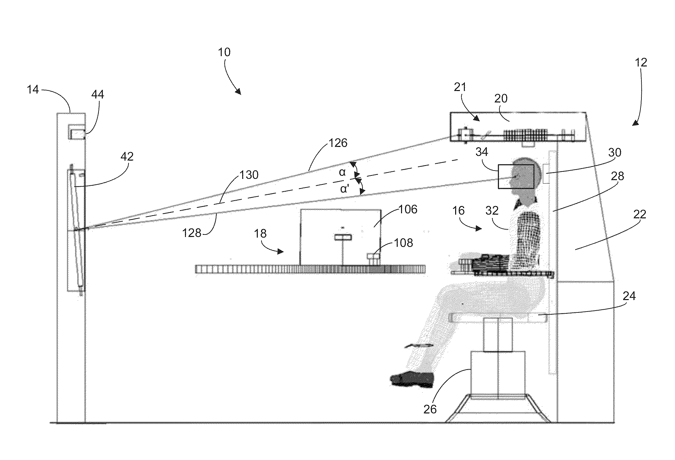
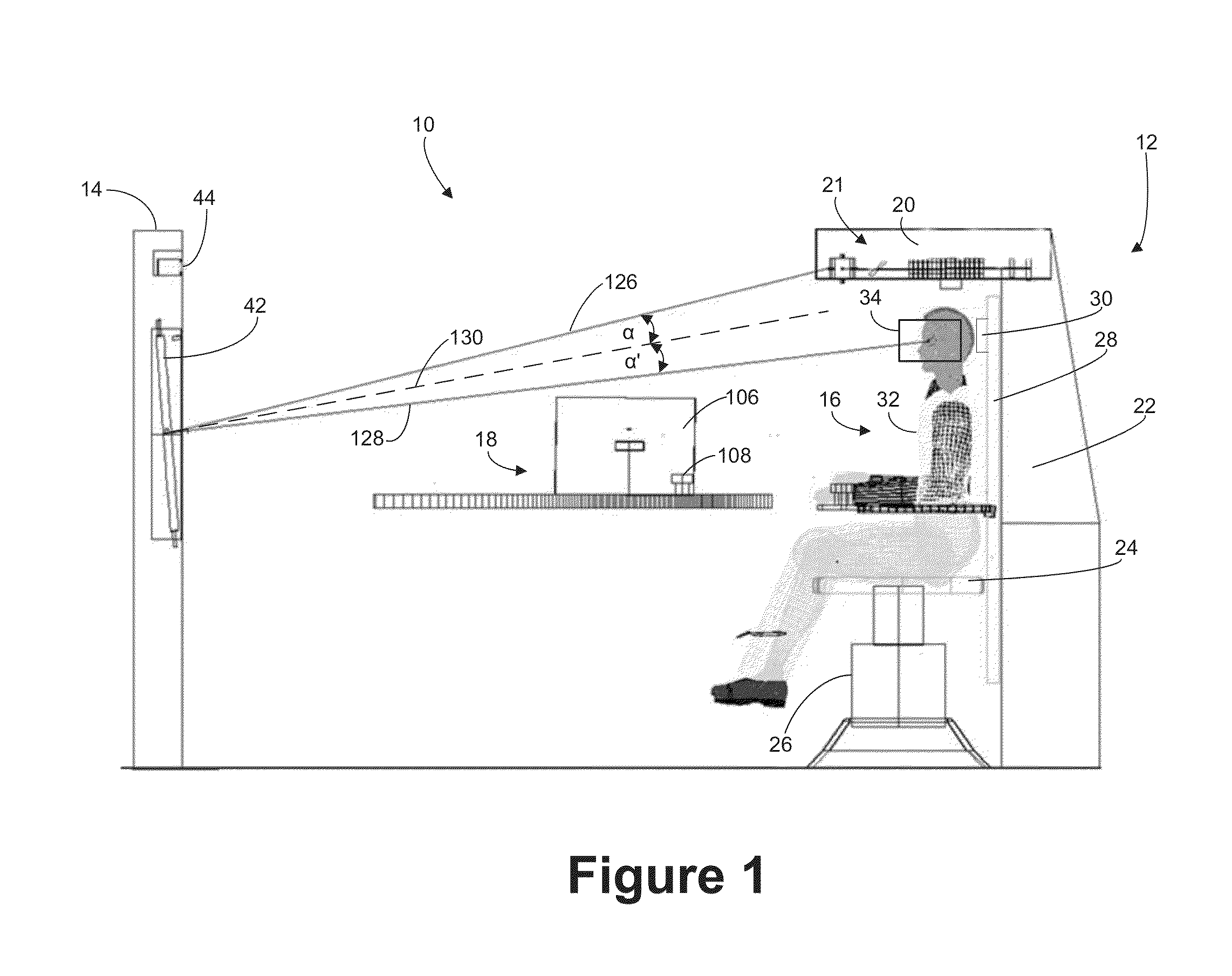
[0023]The present systems and methods are directed generally to a vision testing system that remotely creates and projects a corrected image to the eyes of a patient being tested. In general, the system is comprised of a patient testing unit and a re...


PUM


Abstract

A vision testing system comprises a image wavefront modulator, eye tracking system, focusing system using a spherical concave mirror, and a patient station. In various embodiments, the image wavefront modulator and the patient's eyes are positioned off axis with respect to the optical axis of the focusing mirror. Thus, optical elements in the wavefront modulator may automatically adjust to correct for aberrations introduced by the focusing system. Moreover, the optical elements may also be used to automatically correct for magnification errors introduced by movement of the patient within the patient testing station. Furthermore, the eye tracking system may be used to determine the errors introduced by movement of the patient eyes. Finally, the wavefront modulator may be used to produce an image on the patient's retina that accurately emulates an image that result if the patient was looking through a spectacle lens of a particular design during various gaze angles.

Description

CLAIM OF PRIORITY[0001]This application claims the benefit of, and incorporates by reference in its entirety, U.S. Provisional Patent Application No. 61 / 604,310, filed Feb. 28, 2012.FIELD OF THE INVENTION[0002]This invention relates generally to systems and methods for vision testing, and more particularly to systems and methods for measuring aberrations in a patient's vision and in emulating corrective modalities including spectacle lenses to allow the patient to analyze multiple lens designs such as multi-focal spectacle lenses, or progressive add lenses (PALs).BACKGROUND[0003]Current vision testing devices that use phoropter technology require that the testing device be positioned intermediate the patient and an image projected on a wall or screen. The phoropter is cumbersome and it commonly introduces instrument accommodation errors in the test results. Moreover, systems that use concave mirrors for reflecting images to the patient typically introduce higher and lower order aber...

Claims


Application Information

Patent Timeline
Patent Type & Authority Applications(United States)
IPC IPC(8): A61B3/18
CPCA61B3/18A61B3/103A61B3/0025A61B3/0083
Inventor THOMPSON, KEITH P.GARCIA, JOSE R.
Owner DIGITALVISION
Why Eureka
Try Eureka