Contact lens optimizer

a technology of optimizing lenses and optimizing lenses, applied in medical science, diagnostics, skiascopy, etc., can solve problems such as poor contrast and glare, inconvenient and costly patient replacement of many lenses to achieve satisfactory vision, and achieve minimal visual side effects and optimal eyesight.

Inactive Publication Date: 2013-08-29
DIGITALVISION
View PDF1 Cites 20 Cited by
  • Summary
  • Abstract
  • Description
  • Claims
  • Application Information

AI Technical Summary

Benefits of technology

[0029]The disclosure teaches the ability to test the tolerance of prospective contact lens patients to different contact lens designs over a range of different distances and viewing conditions. This permits contact lens emulation under natural conditions, void of obstructing instrume

Problems solved by technology

A disadvantage to diffractive designs is that poor contrast and glare are often problems.
As more and more presbyopia correcting contact lenses become available, eye care professionals and their patients are exposed to an expanding number of choices and marketing claims that are difficult to evaluate objectively.
Clinical experience with presbyopia-correcting-contact lenses has demonstrated that not all patients are good candidates for these lenses and are dissatisfied with their vision requiring the contact lenses to be replaced by a lens of different design.
Trying on and replacing numerous lenses to attain satisfactory vision is inconvenient and costly for patients.
Those patients with large amounts of pre-existing spherical aberration will notice a substantial decline in night vision with the lens designs that do not correct, or that worsen, the spherical aberration in the periphery of the pupil compared to lens designs that provide for substantial correction of the spherical aberration.
These lenses were tested with an expensive specialty optical instrument not available to most practitioners.
Therefore, prior art means of fitting contact lenses fail to provide the practitioner with information needed to select the best corrective contact lens design for a par

Method used


Image

  • Contact lens optimizer
  • Contact lens optimizer
  • Contact lens optimizer

Examples


Embodiment Construction

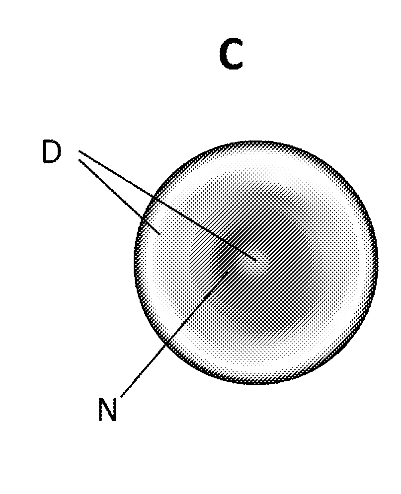
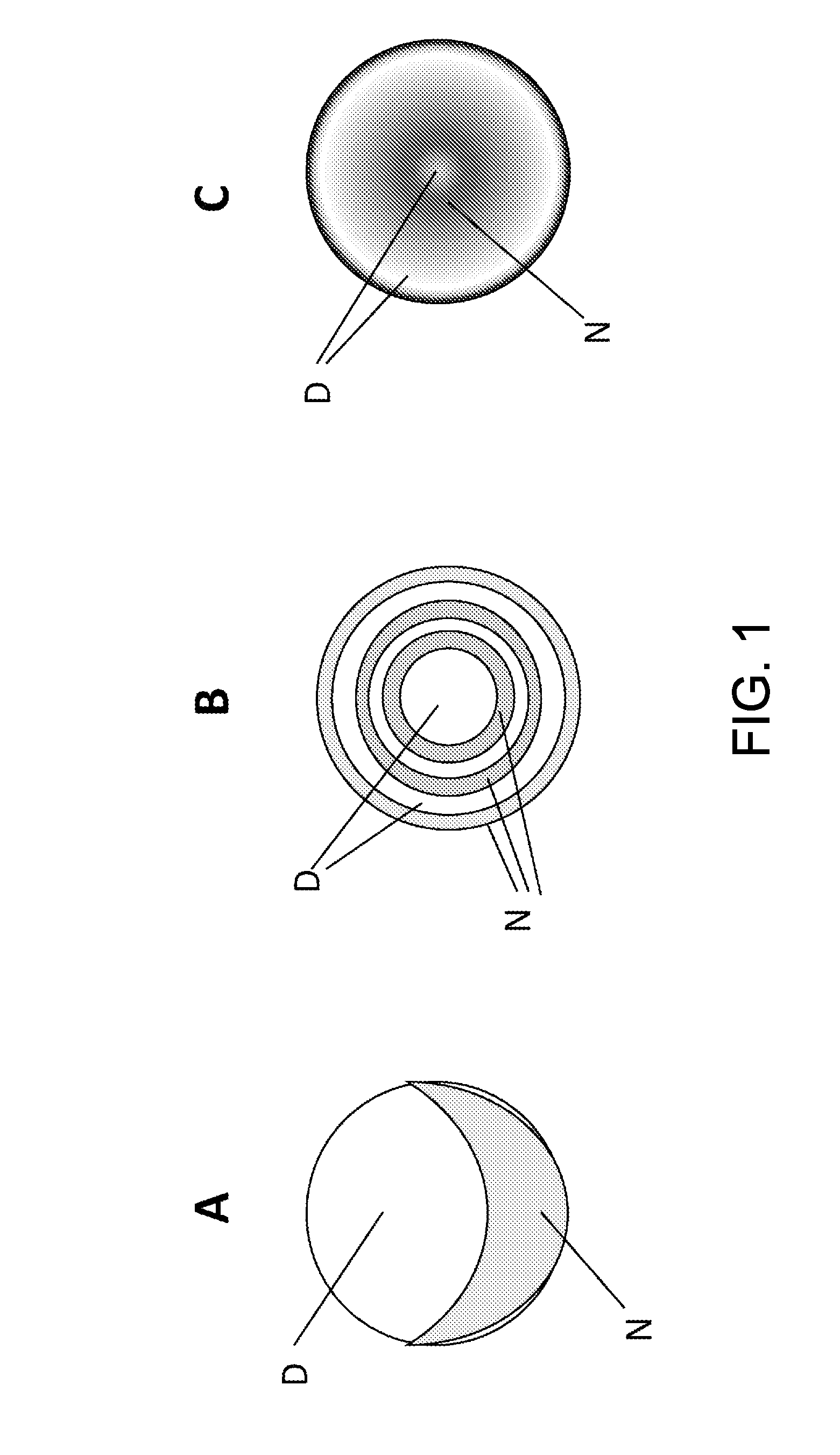
[0042]One embodiment of the apparatus has two components. A contact lens measurement means is used to characterize the optical properties of one or more contact lenses and to determine the modulation of the wavefront of an image that is necessary to reproduce or to emulate the optical properties of the contact lens once it is placed on the cornea of a patient's eye. The second component is a contact lens emulator means that recreates the optical properties of the contact lens for patient testing. In an alternative embodiment, the optical properties of the contact lens are provided elsewhere.

[0043]FIG. 1 shows three multi-focal contact lenses A, B, C that have different optical designs. Three lenses are shown for exemplary purposes to illustrate the three major types of presbyopia correcting contact lenses in use today; bi-focal, diffractive, and refractive. The instrument is not limited to emulating these types of designs and it may be used to emulate future designs that are develop...


PUM


Abstract

Vision testing methods and apparatuses are disclosed, the methods including measuring the modulation to a wavefront of light imparted by a contact lens, determining the wavefront modulation necessary to emulate the optical properties of the lens as worn on a patient's eye, generating a static or dynamic image viewable by a patient, modulating the wavefront of the image remote from the patient to attain the wavefront necessary to emulate the optical properties of the lens as worn on a patient's eye, and relaying the wavefront to a plane nearby, on, or within the patient's eye. The apparatuses include devices for measuring the modulation to a wavefront of light imparted by a contact lens, determining the wavefront modulation necessary to emulate the optical properties of the lens as worn on the patient's eye, generating a static or dynamic image viewable by a patient, modulating the wavefront of the image remote from the patient to attain the wavefront necessary to emulate the optical properties of the lens as worn on the patient's eye, and relaying the wavefront to a plane nearby, on, or within the patient's eye.

Description

BACKGROUND OF THE DISCLOSURE[0001]1. Field[0002]Disclosed is a method and apparatus of simulating the optical properties of one or more contact lenses as worn on the patient's eye under real-world conditions at far away, close, and intermediate distances, and under monocular or binocular viewing conditions.[0003]2. Description of the Related Art[0004]The first known contact lens was fabricated and fit in the late 1800's. By the middle of the twentieth century, plastic lenses were devised and made smaller, thinner, and with designs that improved comfort and vision. Hard lenses remained difficult for many patients to wear and the first commercially available soft contact lens made of a water absorbing plastic known as hydroxyl-ethylmethacrylate (HEMA) was introduced by Baush & Lomb in 1971. The soft lenses were thinner and much more comfortable, allowing many more patients to become successful contact lens wearers. Today, approximately 90% of contact lenses sold in the United States a...

Claims


Application Information

Patent Timeline
IPC IPC(8): A61B3/10
CPCA61B3/032A61B3/1015A61B3/103A61B3/0025G02C7/04A61B3/028A61B3/0041
Inventor THOMPSON, KEITH P.GARCIA, JOSE R.
Owner DIGITALVISION
Why Eureka
Try Eureka