Eureka AIR delivers breakthrough ideas for toughest innovation challenges, trusted by R&D personnel around the world.

Optical apparatus and operating method thereof

Active Publication Date: 2013-08-29
CRYSTALVUE MEDICAL
View PDF3 Cites 1 Cited by
  • Summary
  • Abstract
  • Description
  • Claims
  • Application Information

AI Technical Summary

Benefits of technology

The invention is a new optical apparatus and operating method that enhances the speed of changing the optical path of the reference light to increase optical detection efficiency using non-destructive and non-contact optical interference technology. The reference light reflection module is designed to be modular rotary, with adjustable length and number of rotation elements based on different detection items and objects to be detected, effectively enhancing the elasticity of the optical device's performance. When used to measure human's axial length, the reference light reflection module can adjust its position relative to the person's factors of race, age, gender, and residence area, allowing for accurate data retrieval and medical diagnosis.

Problems solved by technology

However, because the combination mechanism of the reflection mirror 14 and the scanning platform used in the conventional optical interference detection apparatus 1 fails to provide the function of rapidly changing the optical path of the reference light, the detection efficiency of the conventional optical interference detection apparatus 1 is not good enough.

Method used


Image

  • Optical apparatus and operating method thereof
  • Optical apparatus and operating method thereof
  • Optical apparatus and operating method thereof

Examples


Embodiment Construction

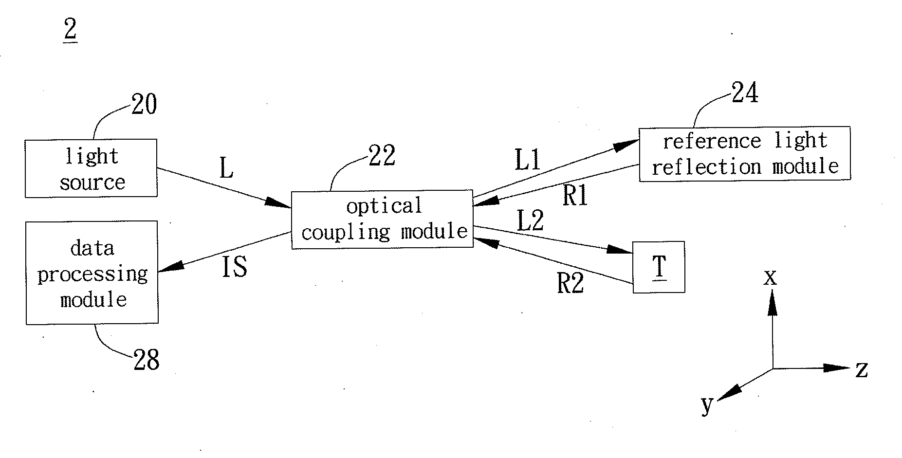
[0028]A preferred embodiment of the invention is an optical apparatus. In this embodiment, the optical apparatus can be an optical image detection apparatus, but not limited to this. In fact, the optical apparatus can be an optical coherence tomography scanner or other similar equipments without specific limitations.

[0029]Please refer to FIG. 2. FIG. 2 illustrates a function block diagram of the optical apparatus in this embodiment. As shown in FIG. 2, the optical apparatus 2 is used to perform optical detection on the object T through optical interference technology. The optical apparatus 2 includes a light source 20, an optical coupling module 22, a reference light reflection module 24, and a data processing module 28. Wherein, the data processing module 28 is coupled to the optical coupling module 22.

[0030]In this embodiment, the light source 20 is used to provide an incident light L and the incident light L is emitted to the optical coupling module 22. When the optical coupling ...


PUM


Abstract

An optical apparatus includes a light source, an optical coupling module, a reference light reflection module, and a data processing module. The light source provides an incident light. The optical coupling module divides the incident light into a reference light and a detection light emitting to the reference light reflection module and the object respectively. The reference light reflection module reflects the reference light and rapidly change the optical path of the reference light. The optical coupling module receives a first reflected light generated by the reference light reflection module reflecting the reference light and a second reflected light generated by the object reflecting the detection light and it interferes the first reflected light and second reflected light to generate a light interference signal. The data processing module receives and analyzes the light interference signal to obtain an optical detection result related to the object.

Description

BACKGROUND OF THE INVENTION[0001]1. Field of the Invention[0002]The invention relates to optical detection, and in particular, to an optical apparatus capable of rapidly changing optical path of the reference light to effectively enhance detection efficiency and an operating method thereof.[0003]2. Description of the Prior Art[0004]In recent years, with the progress of the optical detection technology, the optical image scanning technology provides a non-invasive way to know the structure and the composition of the organizations of the object to be detected. Because it is rapid and non-invasive, it is widely applied to many regions, especially human body function detection and medical diagnostic.[0005]Please refer to FIG. 1. FIG. 1 shows basic structure of the conventional optical interference detection apparatus. As shown in FIG. 1, the conventional optical interference detection apparatus 1 changes the position of the reflection mirror 14 (moving parallel to the z-direction in FIG...

Claims


Application Information

Patent Timeline
IPC IPC(8): G01B9/02
CPCG01B9/02015
Inventor YEN, MENG-SHINWANG, WILLIAMCHOU, CHUNG-CHENGLIN, CHUN-NAN
Owner CRYSTALVUE MEDICAL
Why Eureka
Eureka Blog
Learn More