Eureka AIR delivers breakthrough ideas for toughest innovation challenges, trusted by R&D personnel around the world.

Display device and backlight unit

Inactive Publication Date: 2008-02-28
SAMSUNG ELECTRONICS CO LTD
View PDF2 Cites 4 Cited by
  • Summary
  • Abstract
  • Description
  • Claims
  • Application Information

AI Technical Summary

Benefits of technology

[0008]Accordingly, it is an exemplary aspect of the present invention to provide a display device with increased optical efficiency and good color reproducibility, and a backlight unit for use in the display device.
[0010]According to an aspect of the present invention, the display device further comprises a light direction changing part that is disposed between the laser light source part and the hologram part and adjusts a direction of light emitted from the laser light source part so that the light is incident at a predetermined angle with respect to a plane of the hologram part in order to obtain a high optical efficiency.
[0015]According to another aspect of the present invention, the laser light sources comprise a nonlinear light modulator using a laser diode having a high optical efficiency.

Problems solved by technology

However, some of the light emitted from the backlight unit is absorbed or reflected by the color filter layer, which results in high optical loss or low optical efficiency.

Method used


Image

  • Display device and backlight unit
  • Display device and backlight unit
  • Display device and backlight unit

Examples


Embodiment Construction

[0028]Reference will now be made in detail to exemplary embodiments of the present invention, examples of which are illustrated in the accompanying drawings, wherein like reference numerals refer to like elements throughout. The exemplary embodiments are described below so as to explain the present invention by referring to the figures. The like elements will be described for a first exemplary embodiment and may not be further described for other embodiments.

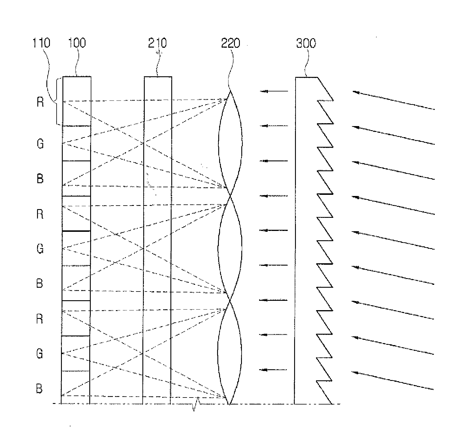
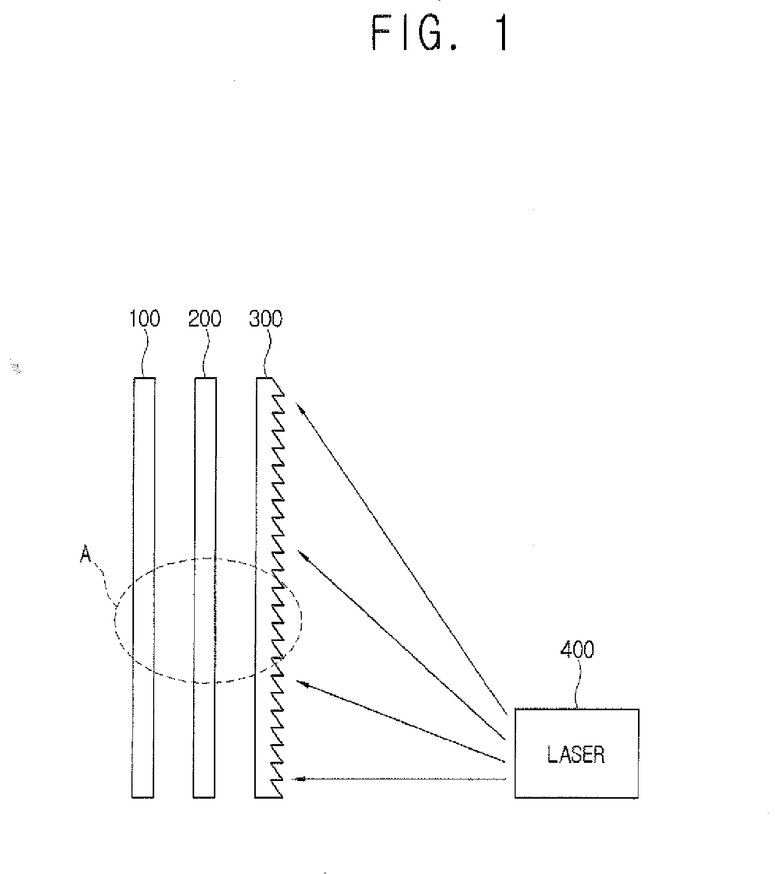
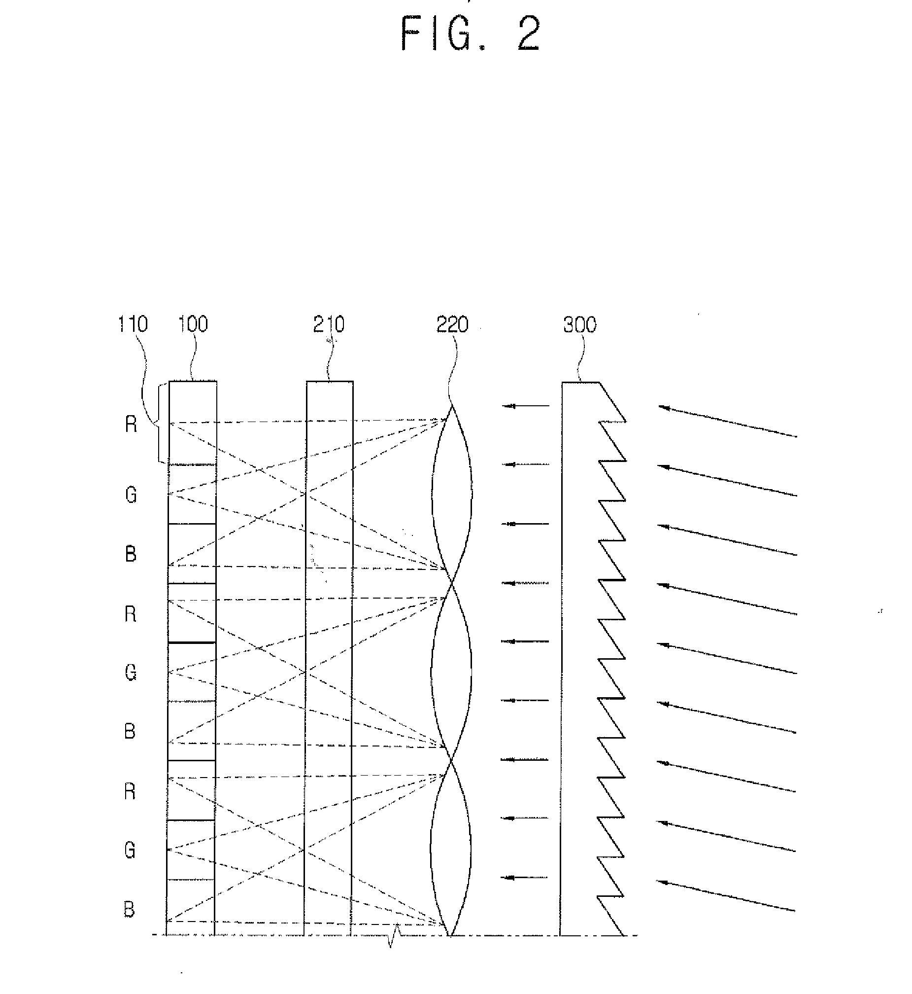
[0029]Hereinafter, a display according to a first embodiment of the present invention will be described with reference to FIGS. 1 to 3. As shown in FIG. 1, a display device comprises a liquid crystal panel 100, a hologram part 200, a light direction changing part 300 and a laser light source part 400. In this embodiment, the display device comprises an LCD device that comprises the liquid crystal panel 100. However, it should be understood that the display device is not limited to an LCD device, but the spirit of the present inv...


PUM


Abstract

A display device is provided, including: a display panel; a hologram part that is disposed behind the display panel; and a laser light source part that is behind the hologram part and provides light to the hologram part.

Description

CROSS-REFERENCE TO RELATED PATENT APPLICATIONS[0001]This application claims priority from Korean Patent Application No. 2006-0080687, filed on Aug. 24, 2006, the disclosure of which is incorporated herein by reference in its entirety.BACKGROUND OF THE INVENTION[0002]1. Field of the Invention[0003]Apparatuses consistent with the present invention relate to a display device and a backlight unit, and more particularly, to a display device with no color filter layer, and a backlight unit for use in the display device.[0004]2. Description of the Related Art[0005]Recently, flat display devices such as liquid crystal displays (LCDs), plasma display panels (PDPs), organic light emitting diodes (OLEDs), and the like have been developed to replace existing cathode ray tube (CRT) technology. Among these new developments, the range of applications of LCDs has spread to office automation equipment, audio / video equipment, and the like.[0006]An LCD comprises a liquid crystal panel that comprises a...

Claims


Application Information

Patent Timeline
IPC IPC(8): G02B5/32
CPCG02B5/32G02B27/0944G02B27/42G02B27/425G02F1/133621G02B19/0014H04N9/3129G02B19/0057G02B19/0009G02B19/0028G02F2001/133607G02F1/133607G02F1/1335
Inventor LEE, JONG-SOOCHO, KUN-HO
Owner SAMSUNG ELECTRONICS CO LTD
Why Eureka
Eureka Blog
Learn More