Eureka AIR delivers breakthrough ideas for toughest innovation challenges, trusted by R&D personnel around the world.

Light emitting device

Active Publication Date: 2018-03-29
NICHIA CORP
View PDF8 Cites 0 Cited by
  • Summary
  • Abstract
  • Description
  • Claims
  • Application Information

AI Technical Summary

Benefits of technology

The present patent text describes a liquid-crystal display device with color filters for red, green and blue, and a light emitting device that transmits light to display an image. The text identifies a problem with current light sources that have a narrow emission peak in the green light region, which negatively affects color purity. To solve this problem, the patent proposes a light source with a half value width in each wavelength region of red, green, and blue that reduces the influence of neighboring wavelength regions and improves color reproduction. The technical effect of this patent is a broader range of color reproduction in a liquid-crystal display device, achieved through the use of a light emitting device with a narrow emission peak in the green light region.

Problems solved by technology

Consequently, it is difficult to use the light emission device using a β-sialon fluorescent material as a light source for a high-definition liquid-crystal display device that is required to have a broader range of color reproducibility.

Method used


Image

  • Light emitting device
  • Light emitting device
  • Light emitting device

Examples


examples

[0066]The present invention will now be described in detail with reference to examples, but the present invention is not limited to these examples.

Fluorescent Material

[0067]Prior to production of light emitting devices of Examples and Comparative Examples, green emitting fluorescent materials and red emitting fluorescent materials were prepared.

[0068]As the green emitting fluorescent materials, first fluorescent materials (I) and other fluorescent materials were prepared. As the first fluorescent materials (I), fluorescent materials A-1 to A-5, and as the other green emitting fluorescent materials, fluorescent materials A-6 to A-10, fluorescent material B, fluorescent material C and fluorescent material D were prepared, as shown in Table 1.

Fluorescent Material A-1

[0069]The fluorescent material A-1 is a fluorescent material having a composition represented by the X1aMgbMncAldOa+b+c+1.5d where X1 is Ba, and where the molar compositional ratio was so defined that the subscript a could ...

examples 1 to 5

, Comparative Examples 1 to 8

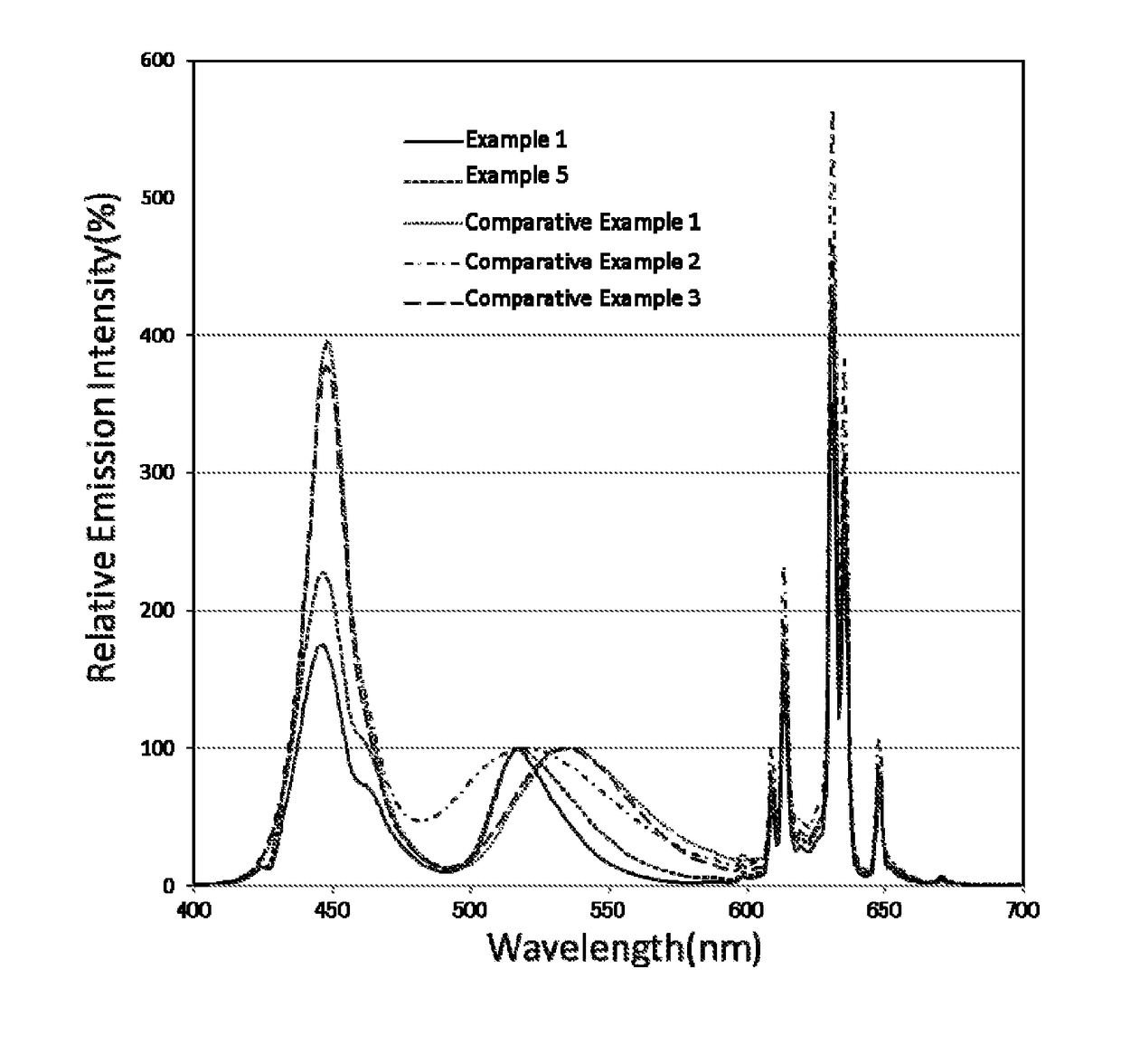
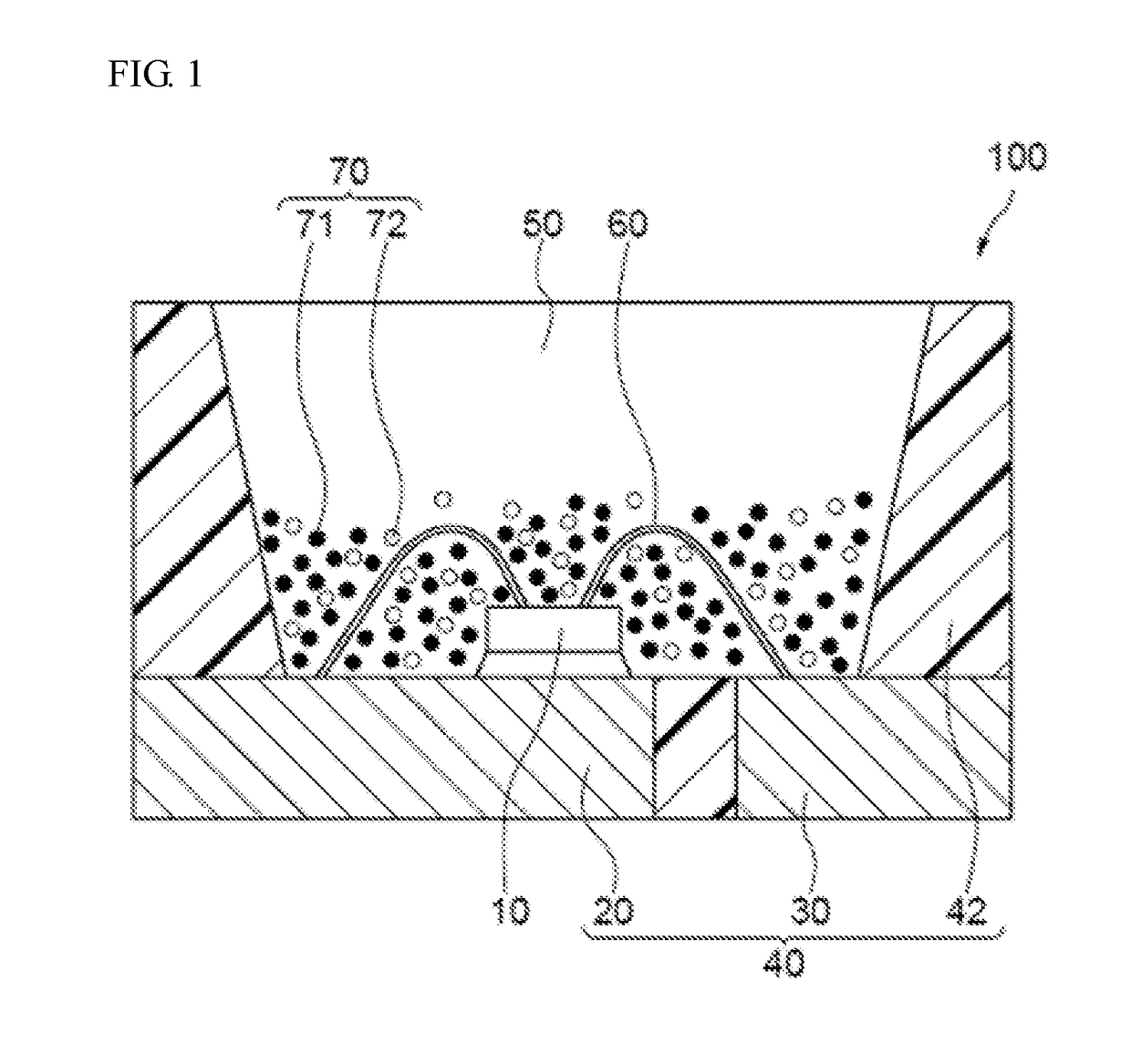
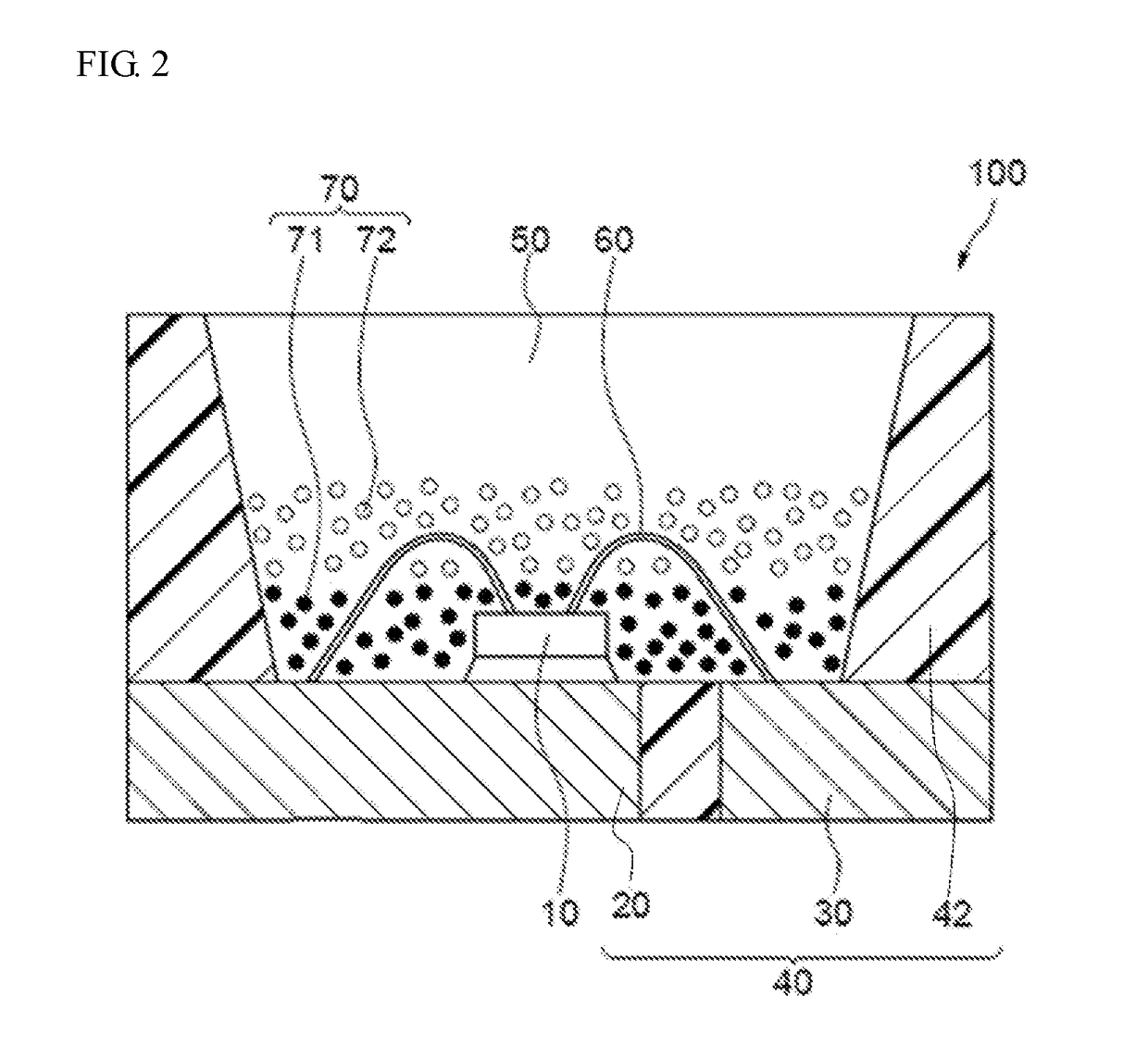
[0093]A green fluorescent material containing a first fluorescent material 71, a red fluorescent material containing KSF as a second fluorescent material 72, and a silicone resin were mixed as dispersed to have a formulation ratio shown in Table 3, and defoamed to prepare a composition for a fluorescent member 50. In Table 3, the ratio of the green fluorescent material and the red fluorescent material to 100 parts by mass of the resin was expressed as “fluorescent material / resin (%)”. In Table 3, the content (% by mass) of the green fluorescent material and the red fluorescent material relative to the total content 100% of the green fluorescent material and the red fluorescent material is shown. The formation ratio of the green fluorescent material and the red fluorescent material in the composition for the fluorescent member was so controlled that the mixed light to be emitted by the light emitting device to be produced could be around x of 0.26 and y o...


PUM


Abstract

Provided is a light emitting device capable of realizing color reproducibility in a broad range. The light emitting device contains a light emitting element having an emission peak wavelength in a range of 430 nm or more and 470 nm or less, a first fluorescent material having a composition represented by formula (I), which has an emission peak wavelength in a range of 510 nm or more and 525 nm or less and has an average particle diameter that is 10.0 μm or more and 30.0 μm or less, and a second fluorescent material having an emission peak wavelength in a range of 620 nm or more and 670 nm or less:X1aMgbMncAldOa+b+c+1.5d  (I)wherein X1 represents at least one element selected from the group consisting of Ba, Sr and Ca, and a, b, c and d satisfy 0.5≦a≦1.0, 0.0≦b≦0.7, 0.3≦c≦0.7, and 8.5≦d≦13.0.

Description

CROSS-REFERENCE TO RELATED PATENT APPLICATION[0001]The present application claims priority under 35 U. S. C. § 119 to Japanese Patent Application No. 2016-191374, filed Sep. 29, 2016, the disclosure of which is hereby incorporated by reference in its entirety.TECHNICAL FIELD[0002]The present disclosure relates to a light emitting device.DESCRIPTION OF RELATED ART[0003]A light emitting device capable of emitting whitish mixed light has been developed, in which a light emitting diode (LED) to emit blue light is combined with a fluorescent material to be excited by the blue light to emit green color and a fluorescent material to emit red color. In the case where a light emitting device is used as an image display device such as a liquid-crystal display device, a light emitting device capable of realizing a large light flux to reproduce colors in a broad range is desired.[0004]For evaluating a color reproducibility range, for example, an NTSC ratio may be employed, which indicates a tel...

Claims


Application Information

Patent Timeline
IPC IPC(8): H01L33/50G02F1/1335
CPCH01L33/504G02F1/133603H01L33/502
Inventor HOSOKAWA, SHOJINISHIMATA, KAZUYAYOSHIDA, TOMOKAZU
Owner NICHIA CORP
Why Eureka
Eureka Blog
Learn More