Light emitting module

Pending Publication Date: 2022-09-08
DARWIN PRECISIONS CORP
View PDF2 Cites 0 Cited by
  • Summary
  • Abstract
  • Description
  • Claims
  • Application Information

AI Technical Summary

Benefits of technology

The present invention aims to provide a light emitting module that can reduce the use of optical films while increasing optical efficiency. This will help to improve the performance of the module and make it more effective in producing high-quality light.

Problems solved by technology

However, the use of optical films would increase the thickness of the light emitting module.
One approach to decrease the thickness of the light emitting module is increasing the amount of LEDs, which would raise cost.

Method used


Image

  • Light emitting module
  • Light emitting module
  • Light emitting module

Examples


Embodiment Construction

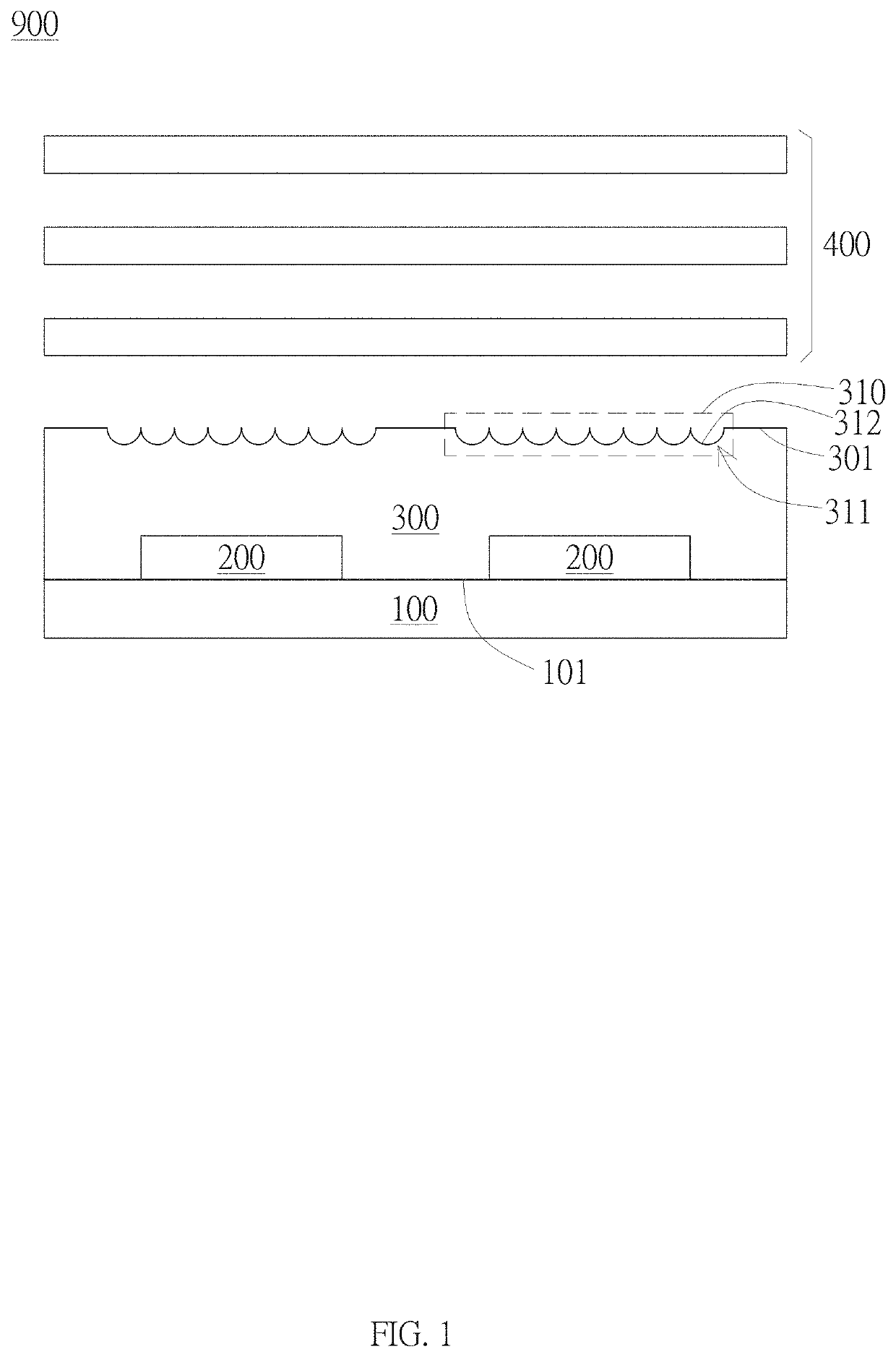
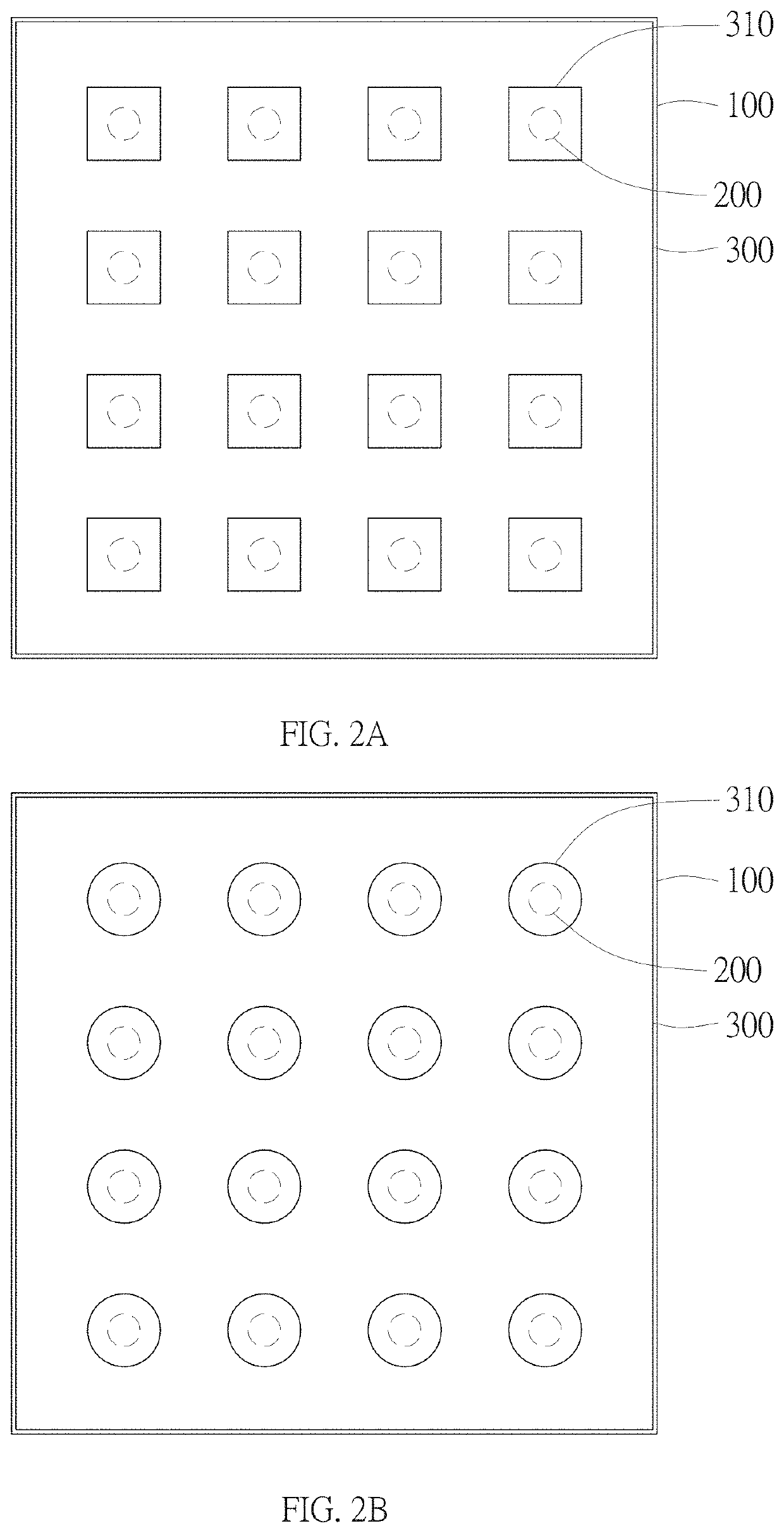
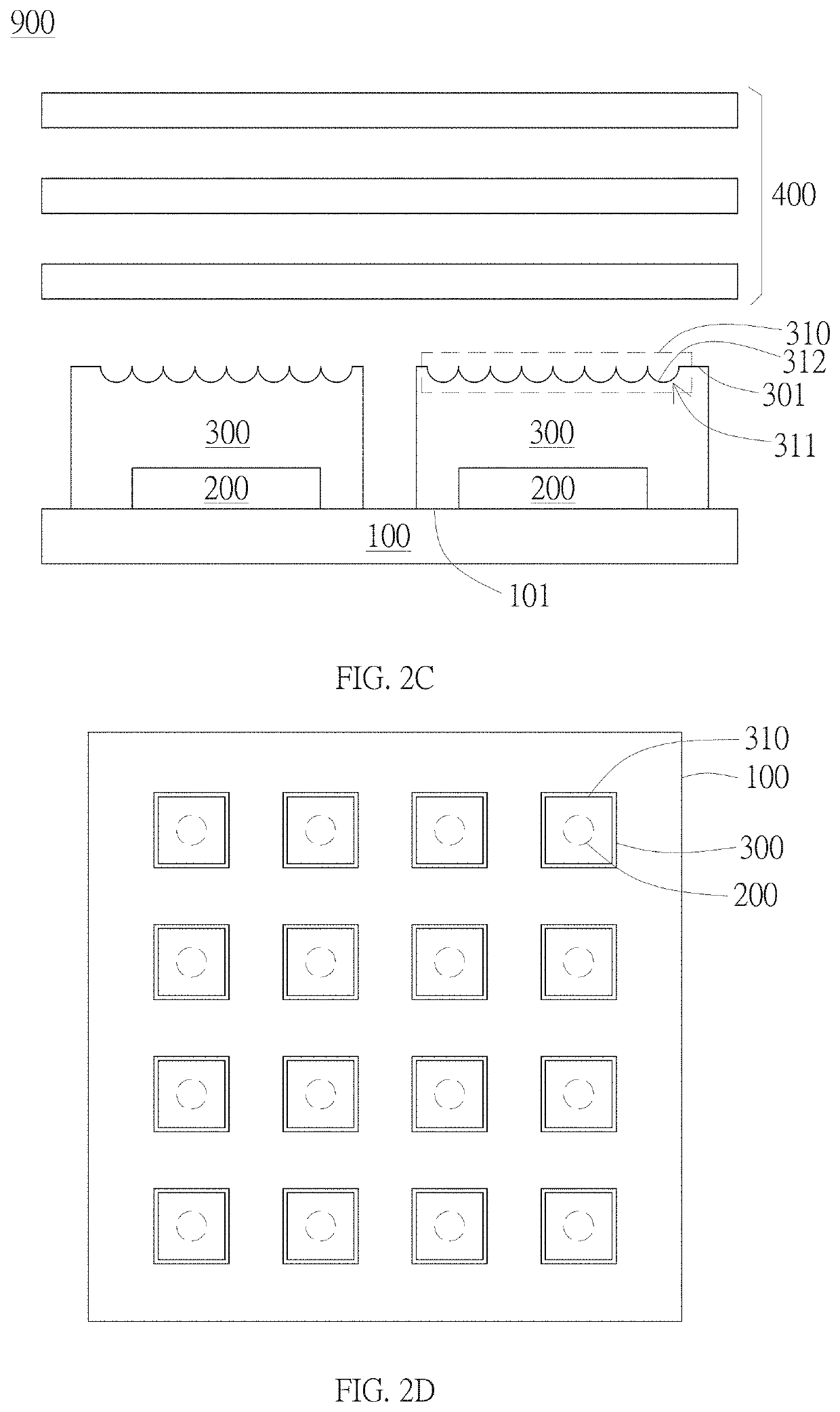
[0013]Implementations of a connection assembly disclosed by the present invention are described below by using particular and specific embodiments with reference to the drawings, and a person skilled in the art may learn of advantages and effects of the present invention from the disclosure of this specification. However, the following disclosure is not intended to limit the protection scope of the present invention, and a person skilled in the art may carry out the present invention by using other different embodiments based on different viewpoints without departing from the concept and spirit of the present invention. In the accompanying drawings, plate thicknesses of layers, films, panels, regions, and the like are enlarged for clarity. Throughout the specification, same reference numerals indicate same elements. It should be understood that when an element such as a layer, film, region or substrate is referred to as being “on” or “connected” to another element, it may be directl...


PUM


Abstract

A light emitting module is disclosed. The light emitting module includes a board, a plurality of light sources, and a package layer. The board includes a first surface. The plurality of light sources are disposed on the first surface. The package layer is disposed on the first surface, which contacts and surrounds the light sources. A plurality of micro-structure areas are defined on the face of the package layer opposite to the first surface, wherein the micro-structure areas are disconnected with each other. The orthographic projection of each micro-structure area on the first surface covers the respective orthographic projection of one of the plurality of light sources on the first surface. The package layer concaves to form a plurality of micro-structures toward the first surface in the micro-structure areas

Description

BACKGROUNDTechnical Field[0001]The present invention relates to a light emitting module, and specifically, to an LED array light emitting module having micro-structure package layer.Related Art[0002]In a conventional design, point light sources such as LEDs are disposed in an array as planar light sources in light emitting modules, wherein optical films such as diffusion plates are usually stacked to uniformize the light to avoid seeing each point light source, i.e., to avoid the so-called “mura” effect. However, the use of optical films would increase the thickness of the light emitting module. One approach to decrease the thickness of the light emitting module is increasing the amount of LEDs, which would raise cost. As such, there is SUMMARY[0003]One of objectives of the present invention is to provide a light emitting module, capable of reducing the amount of optical films and increasing the optical efficiency.[0004]The light emitting module of the present invention includes a b...

Claims


Application Information

Patent Timeline
IPC IPC(8): F21V5/00F21V19/00
CPCF21V5/007F21V19/001F21V5/002H01L33/54H01L33/58H01L25/0753
Inventor CHANG, YU-CHENGHUANG, YU-MING
Owner DARWIN PRECISIONS CORP
Why Eureka
Try Eureka