Knit sleeve for an oil dip stick tube, combination thereof, method of construction thereof and method of dampening the vibration of an oil dip stick tube

Inactive Publication Date: 2013-08-29
FEDERAL MOGUL POWERTAIN LLC
View PDF0 Cites 13 Cited by
  • Summary
  • Abstract
  • Description
  • Claims
  • Application Information

AI Technical Summary

Benefits of technology

[0008]In accordance with another aspect of the invention, a knit sleeve in combination with a vehicle oil dip stick tube configured for sliding receipt of an oil dip stick therein is provided. The knit sleeve includes a circumferentially continuous, closed knit tubular wall extending between opposite ends with a pair of end sections adjacent the opposite ends and a midsection extending between the end sections. The end sections includes heat-shrinkable yarn to allow the end sections to be heat-shrunk into fixed relation about the oil dip stick tube. The midsection includes generally rigid, circumferentially extending, non-h

Problems solved by technology

In some cases, the vibration of the tube can be violent, and thus, can lead to premature failure.
Although the sleeves tend to offer sufficient dampening to the locations about which they are applied, they are cumbersome to install, which adds to the manufacturing cost of the vehic

Method used


Image

  • Knit sleeve for an oil dip stick tube, combination thereof, method of construction thereof and method of dampening the vibration of an oil dip stick tube
  • Knit sleeve for an oil dip stick tube, combination thereof, method of construction thereof and method of dampening the vibration of an oil dip stick tube
  • Knit sleeve for an oil dip stick tube, combination thereof, method of construction thereof and method of dampening the vibration of an oil dip stick tube

Examples


Embodiment Construction

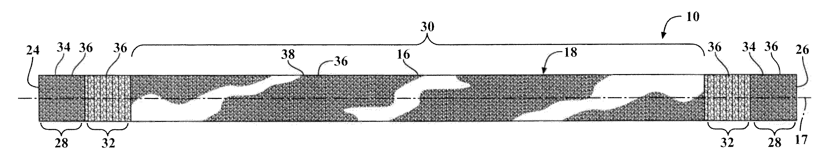
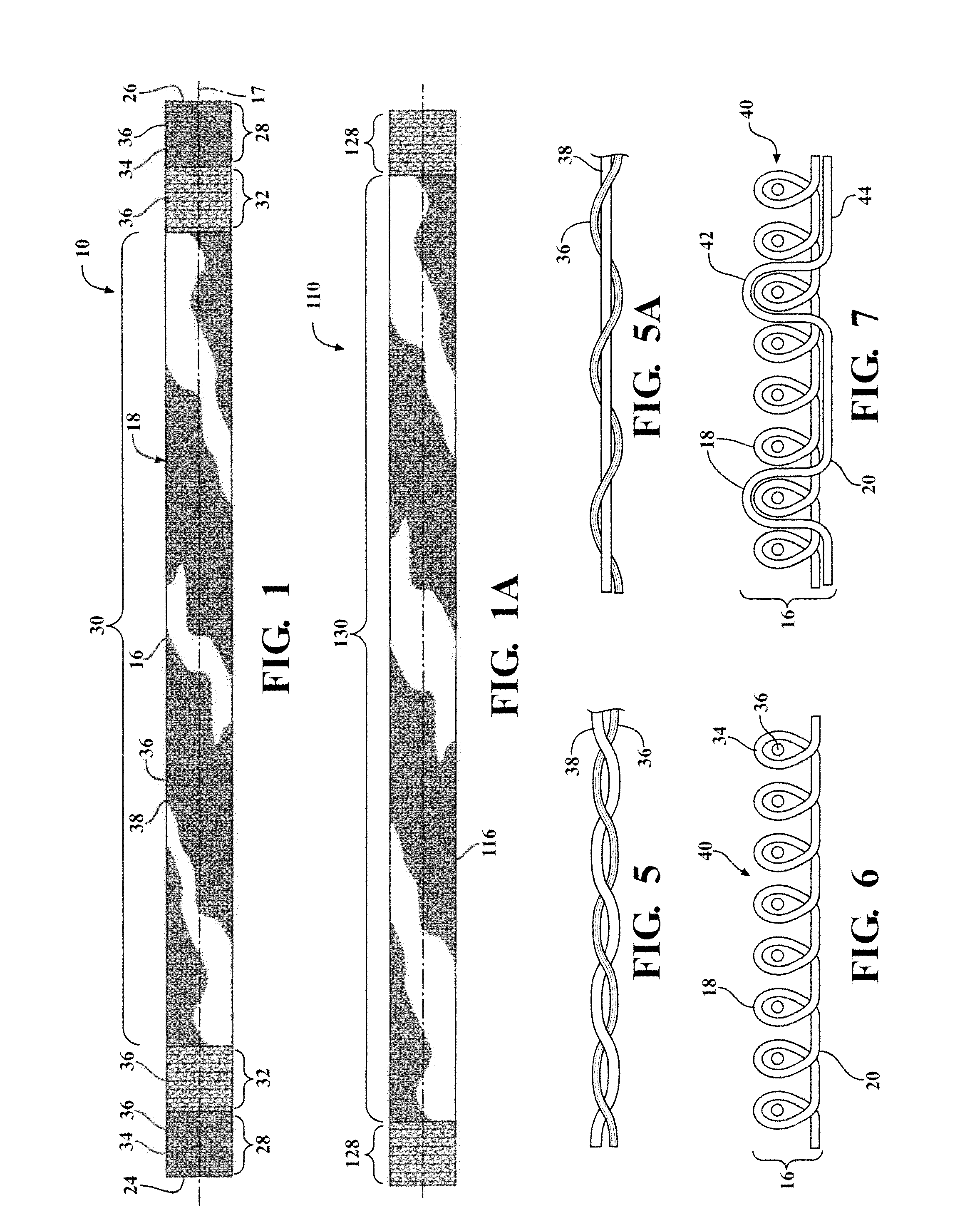
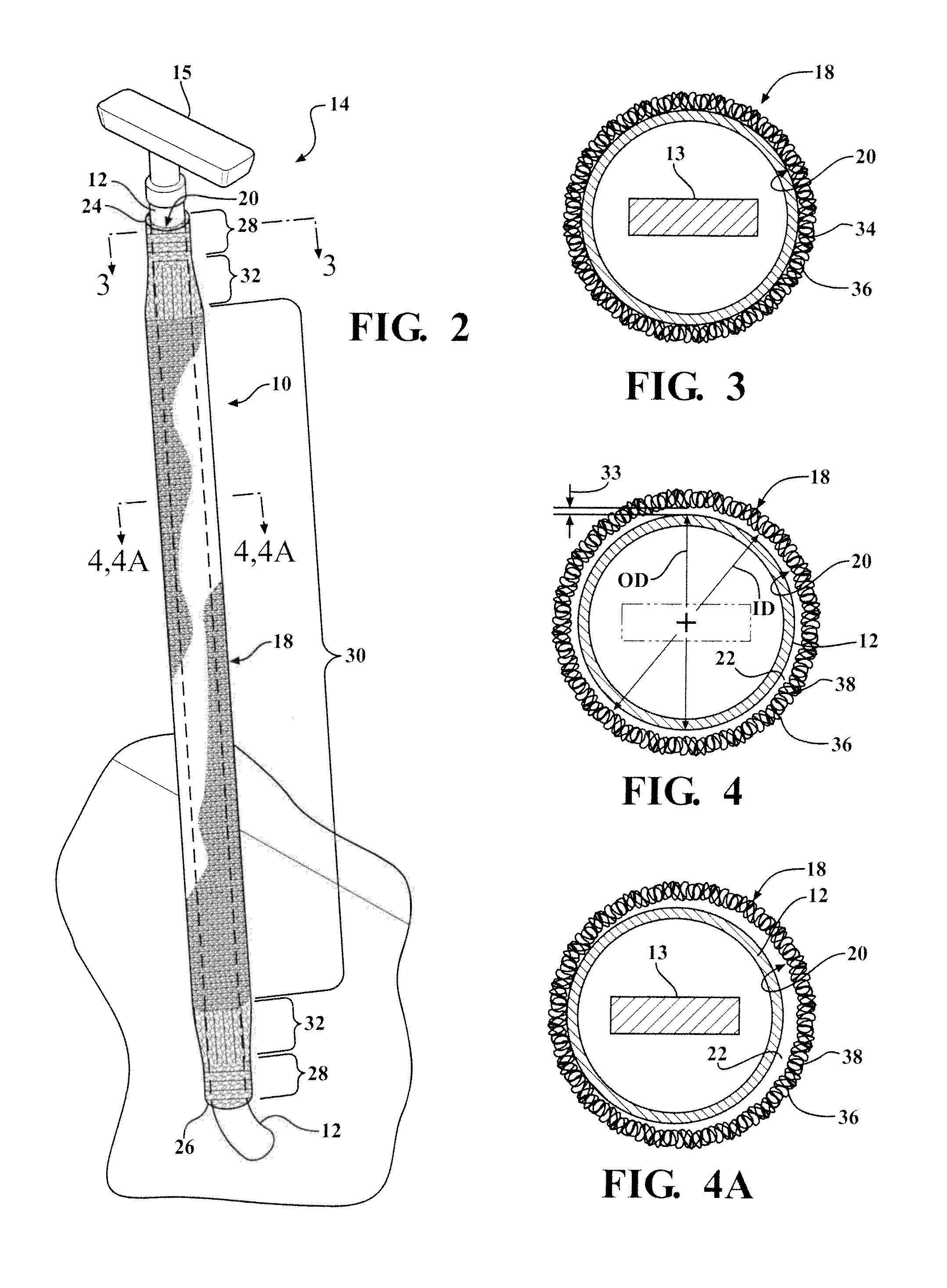
[0021]Referring in more detail to the drawings, FIG. 1 illustrates a circumferentially continuous knit tubular textile sleeve 10 constructed according to one presently preferred embodiment of the invention. As shown in FIG. 2, the sleeve 10 is constructed to be easily disposed about an oil dip stick tube, referred to hereafter as tube 12, which is configured for slideable receipt of an oil dip stick 13, and subsequently fixed thereto to form an oil dip stick tube and sleeve assembly, referred to hereafter as assembly 14, to dampen the harmonic frequency of the tube 12 in a running vehicle. The sleeve 10 extends along a sufficient portion of the tube 12 to perform its dampening function, such as between about 7-12 inches, by way of example and without limitation. The sleeve 10 is shown here as extending along a substantially straight portion of the tube 12 starting immediately adjacent an end of the tube 12 below a dipstick handle 15. As such, the sleeve 10 is typically in plain view...


PUM

PropertyMeasurementUnit
Diameteraaaaaaaaaa
Densityaaaaaaaaaa
Flexibilityaaaaaaaaaa

Abstract

A knit sleeve for an oil dip stick tube, combination thereof, method of construction thereof and method of dampening the vibration of an oil dip stick tube is provided. The knit sleeve includes a circumferentially continuous, closed knit tubular wall extending between opposite ends with a pair of end sections adjacent the opposite ends and a midsection extending between the end sections. The end sections include heat-shrinkable yarn to allow the end sections to be heat-shrunk into a fixed relation about the oil dip stick tube. The midsection includes generally rigid, circumferentially extending, non-heat-shrinkable yarn to maintain the midsection having a circular configuration about the oil dip stick tube with an annular gap extending between the oil dip stick tube and an inner surface of the midsection.

Description

BACKGROUND OF THE INVENTION[0001]1. Technical Field[0002]This invention relates generally to oil dip stick tubes, and more particularly to apparatus and methods for reducing the vibration frequency of oil dip stick tubes.[0003]2. Related Art[0004]Vehicle oil dip stick tubes are generally lengthy tubes that extend from a crankcase of an engine upwardly to a location that is readily accessible. An oil dip stick is slidably received in the dip stick tube so that the dip stick can be removed from the tube to indicate the oil level in the crankcase. In modern engines, wherein room beneath a hood of the vehicle is sparse, the oil dip stick tube typically traverses one or more bends over a number of feet, thereby being routed about engine components in close proximity to one another. Modern engines are constantly being developed to enhance fuel economy. Some engines have been developed to operate at certain speeds with all the engine cylinders functioning, while at other speeds, typically ...

Claims


Application Information

Patent Timeline
IPC IPC(8): B32B1/08B29C71/02D04B1/22
CPCB32B1/08Y10T428/1334D04B1/22G01F23/04D10B2505/12D04B1/12D04B1/225D10B2401/041D10B2403/0333
Inventor MALLOY, CASSIE M.BRASSENX, CHRISTOPHEZHANG, ZHONGHUAILUDY, LINWOODGAO, TIANQI
Owner FEDERAL MOGUL POWERTAIN LLC
Why Eureka
Try Eureka