Locking Plate with Screw Fixation from Opposite Cortex

a technology of locking plate and opposite cortex, which is applied in the field of locking plate, can solve the problems of undesirable dissection of the attachment technique, difficulty in placing screws from the bottom,

Active Publication Date: 2013-08-29
HATCH DANIEL J DPM
View PDF1 Cites 59 Cited by
  • Summary
  • Abstract
  • Description
  • Claims
  • Application Information

AI Technical Summary

Benefits of technology

[0006]The present application provides for methods and apparatuses for supporting a bone (e.g. a bone in a human foot or hand). In some aspects, an apparatus for supporting a bone includes a plate configured for positioning on a tension side of the bone. Two or more fasteners are configured to extend from an opposite side of the bone to the plate, and engage the plate after extending through the bone. The plate has an attachment mechanism operable to engage with the fasteners. In other aspects, a method of performing a surgical procedure includes positioning a plate on a tension side of a bone, and forming a hole from an opposite side of the bone to the plate. A fastener is inserted through the hole to the plate, and the plate is adjusted into position on the bone surface on the tension side of the bone. One or more additional holes are formed from the opposite side of the bone to the plate, and one or more additional fasteners are inserted.

Problems solved by technology

Current systems in foot and ankle surgery include plates or supporting structures that are utilized or located dorsally and on the sides of the bone, primarily due to anatomical constraints.
While the plate can be placed plantarly, difficulties arise when placing screws from the bottom as designed.
This difficulty stems from the concentration of neurovascular structures on the tension side of the bone and surgical exposure.
This attachment technique requires undesirable dissection and / or exposure of the arteries and nerves on the tension side of the bone.

Method used


Image

  • Locking Plate with Screw Fixation from Opposite Cortex
  • Locking Plate with Screw Fixation from Opposite Cortex
  • Locking Plate with Screw Fixation from Opposite Cortex

Examples


Embodiment Construction

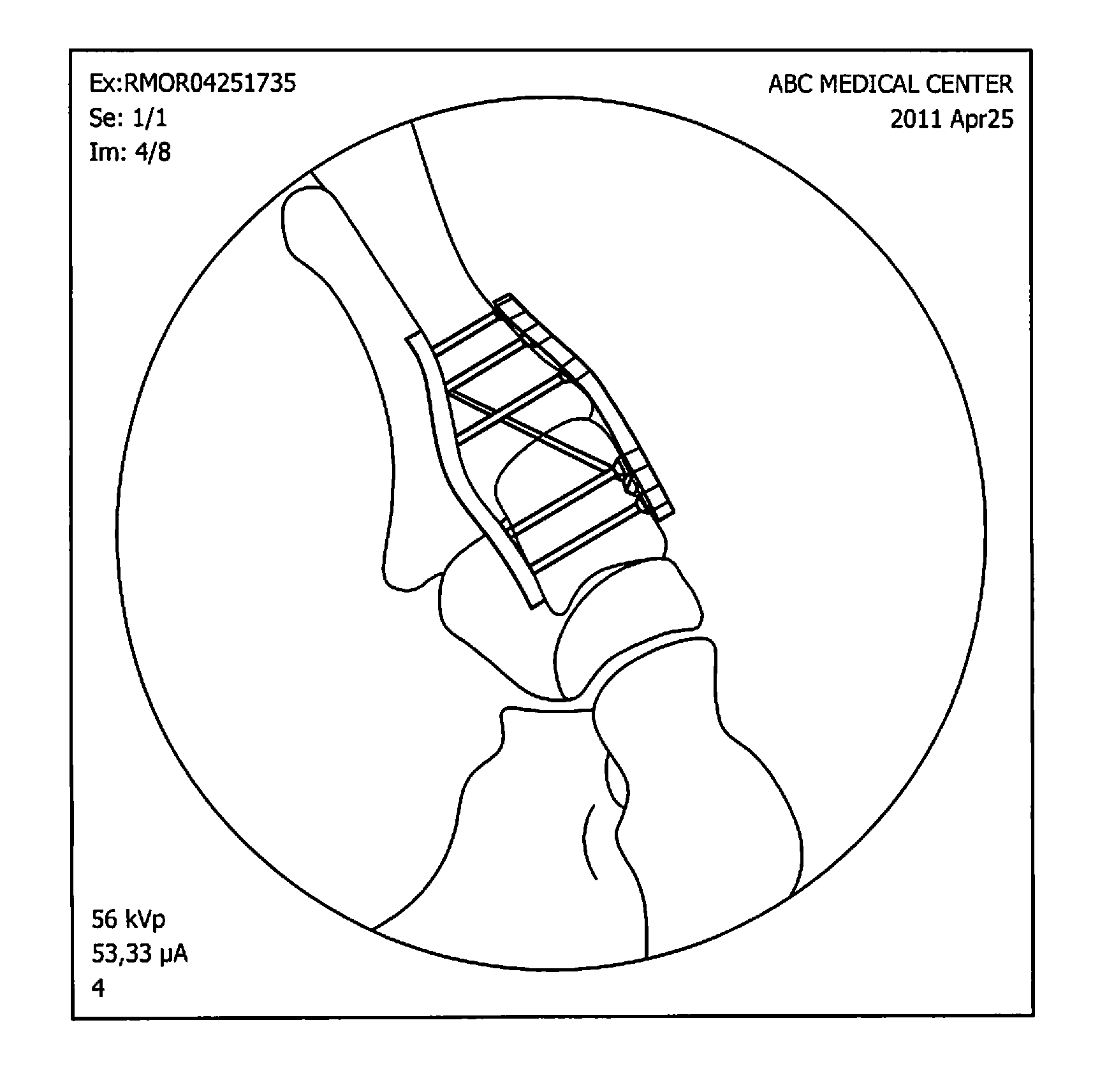
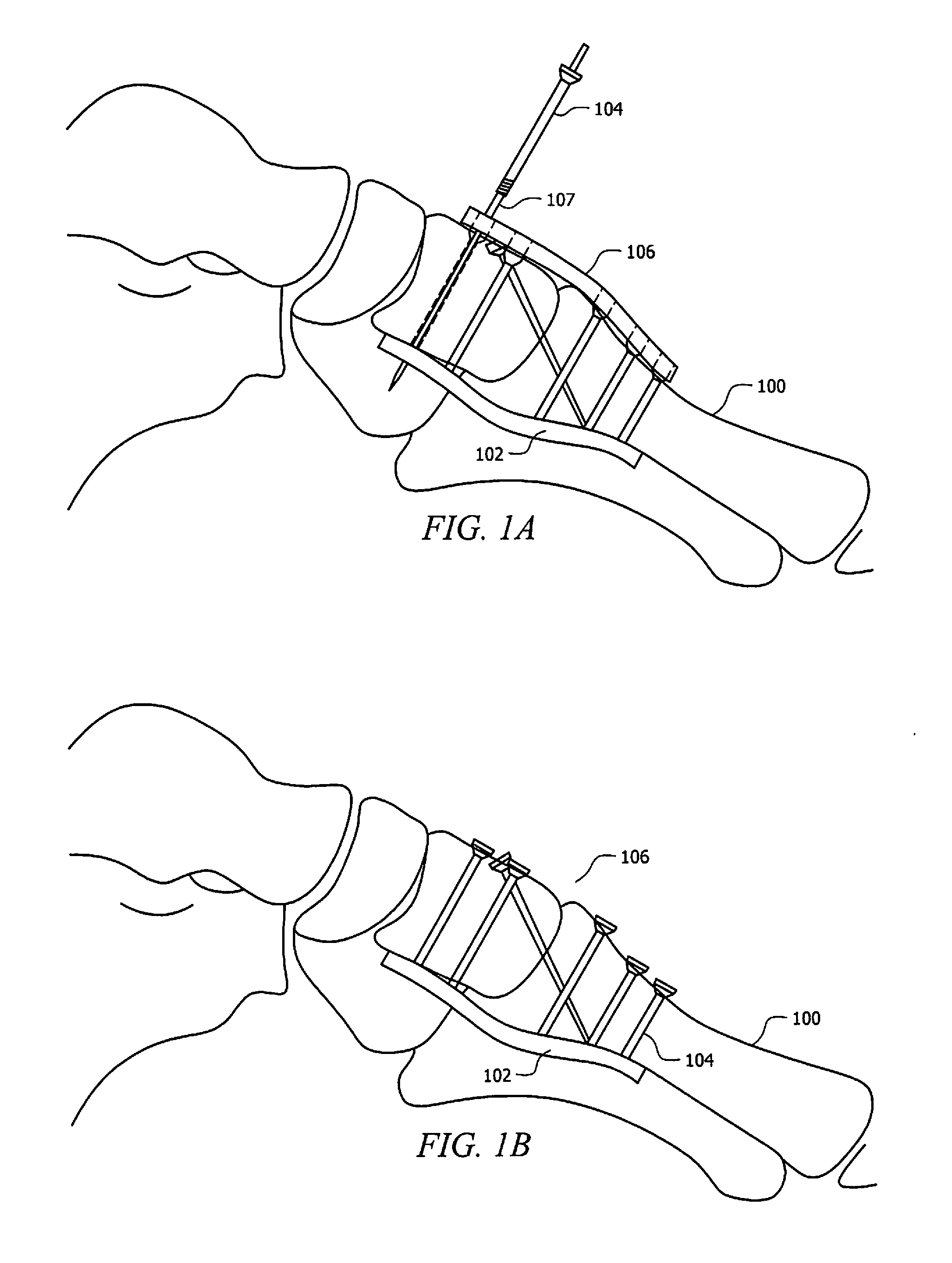
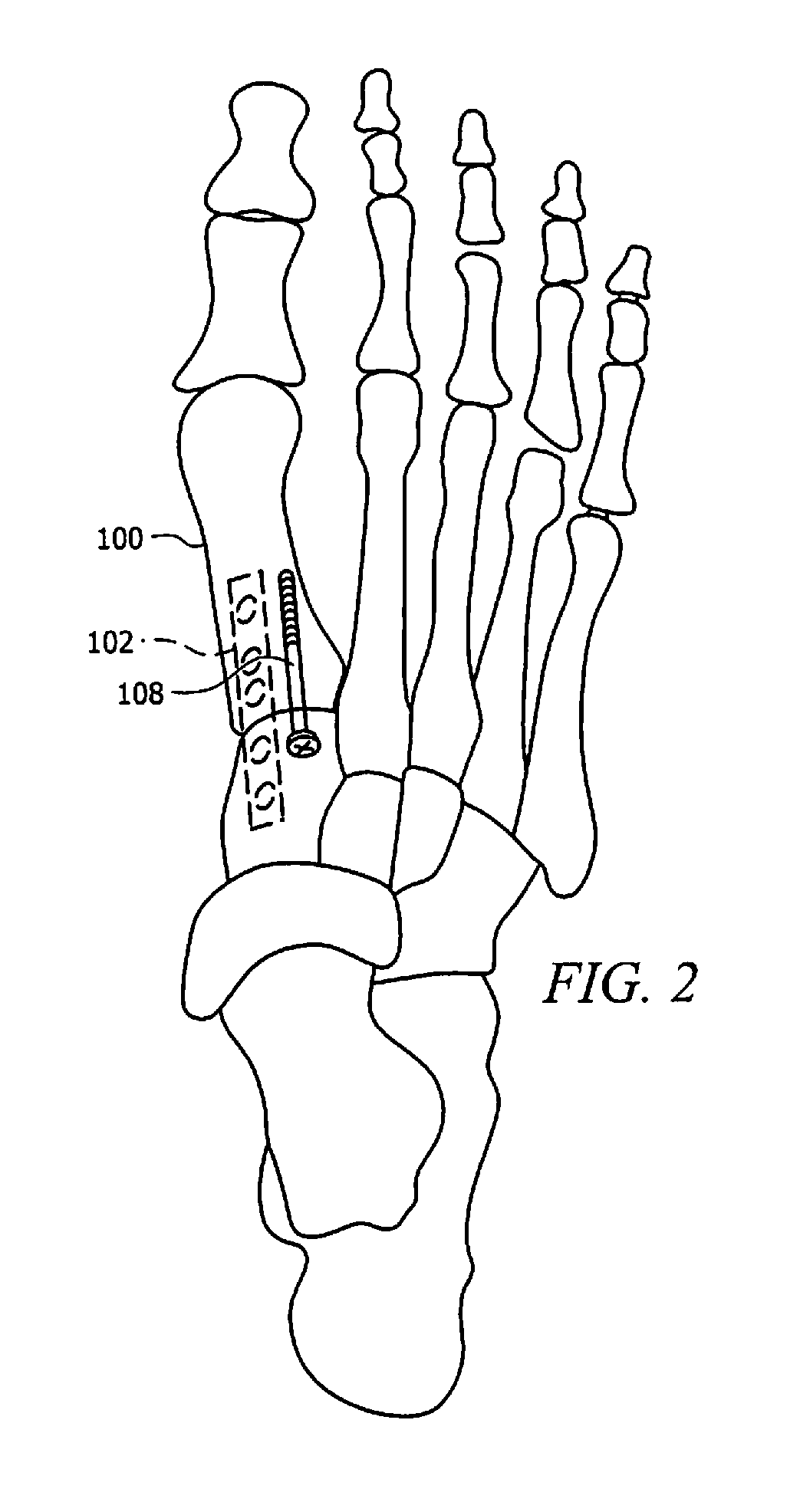
[0028]Referring generally to FIGS. 1A and 1B, a new device is disclosed for supporting a bone 100 (e.g. a bone in a human foot or hand). The device includes a locking plate 102 that is placed at a tension side of the bone 100 and that is attached to the bone by two or more fasteners 104 (e.g., special screws) placed into the bone 100 from a side opposite the locking plate 102. While it is envisioned that some or all of the fasteners 104 may extend directly from the side opposite the locking plate, it is also envisioned that some or all of the fasteners 104 may extend at various angles from the side opposite the locking plate 102. Stated differently, the fasteners 104 need not be perpendicular to a longitudinal axis of the locking plate, and may extend from any region of the bone 100 that is opposite the tension bearing side of the bone 100. Additionally, it is envisioned that one or more heads of the fasteners 104 may protrude (e.g., entirely or partially) above the surface of bone ...


PUM


Abstract

An apparatus for supporting a bone includes a plate configured for positioning on a tension side of the bone. Two or more fasteners are configured to extend from an opposite side of the bone to the plate, and engage the plate after extending through the bone. The plate has an attachment mechanism operable to engage with the fasteners. In other aspects, a method of performing a surgical procedure includes positioning a plate on a tension side of a bone, and forming a hole from an opposite side of the bone to the plate. A fastener is inserted through the hole to the plate, and the plate is adjusted into position on the bone surface on the tension side of the bone. One or more additional holes are formed from the opposite side of the bone to the plate, and one or more additional fasteners are inserted.

Description

CROSS-REFERENCE TO RELATED APPLICATIONS[0001]The present application claims priority to co-pending U.S. Provisional Patent Application Number 61 / 604,909, entitled “PLANTAR LOCKING PLATE WITH SCREW FIXATION FORM OPPOSITE CORTEX,” filed Mar. 23, 2012, the disclosure of which is hereby incorporated herein by reference in its entirety.TECHNICAL FIELD[0002]The present application relates to devices for supporting a bone in a human foot or hand, and relates in particular to a locking plate for positioning on the tension side of bone.BACKGROUND[0003]Plating technology has reached its 4th generation, evolving to locking plate constructs. This system provides little to no contact with the bone, thus preserving blood supply and the periosteum. The screw to plate construct provides a fixed angle, yielding more stability and resistance to pull out.[0004]From a mechanical standpoint, the plate is best utilized and functions the best when placed on the tension side of the bone. In case of foot su...

Claims


Application Information

Patent Timeline
Patent Type & Authority Applications(United States)
IPC IPC(8): A61B17/80
CPCA61B17/80G06K9/00671A61B17/8033G06V20/20
Inventor HATCH, DANIEL J.BECKENDORF, BRANDON
Owner HATCH DANIEL J DPM
Why Eureka
Try Eureka