Work current switching to eliminate arc blow

a technology of work current and arc blowing, applied in the field of welding, can solve problems such as arc blowing, arc instability, and destabilizing the welding ar

Active Publication Date: 2013-09-05
LINCOLN GLOBAL INC
View PDF12 Cites 18 Cited by
  • Summary
  • Abstract
  • Description
  • Claims
  • Application Information

AI Technical Summary

Problems solved by technology

The magnetization of the work piece and / or the work piece fixture can cause the welding arc to deflect or bend from its ideal positioning which can tend to cause arc blow, or otherwise destabilize the welding arc.
However, the use of a single current path throughout a welding operation can also cause arc instability and arc blow issues as the distance and orientation between the welding operation and the ground contact point changes.
Moreover, it can be problematic to have a single current path through the work piece during welding as it can cause the welding arc to be biased to a single orientation during welding.

Method used


Image

  • Work current switching to eliminate arc blow
  • Work current switching to eliminate arc blow
  • Work current switching to eliminate arc blow

Examples


Embodiment Construction

[0016]Exemplary embodiments of the invention will now be described below by reference to the attached Figures. The described exemplary embodiments are intended to assist the understanding of the invention, and are not intended to limit the scope of the invention in any way. Like reference numerals refer to like elements throughout.

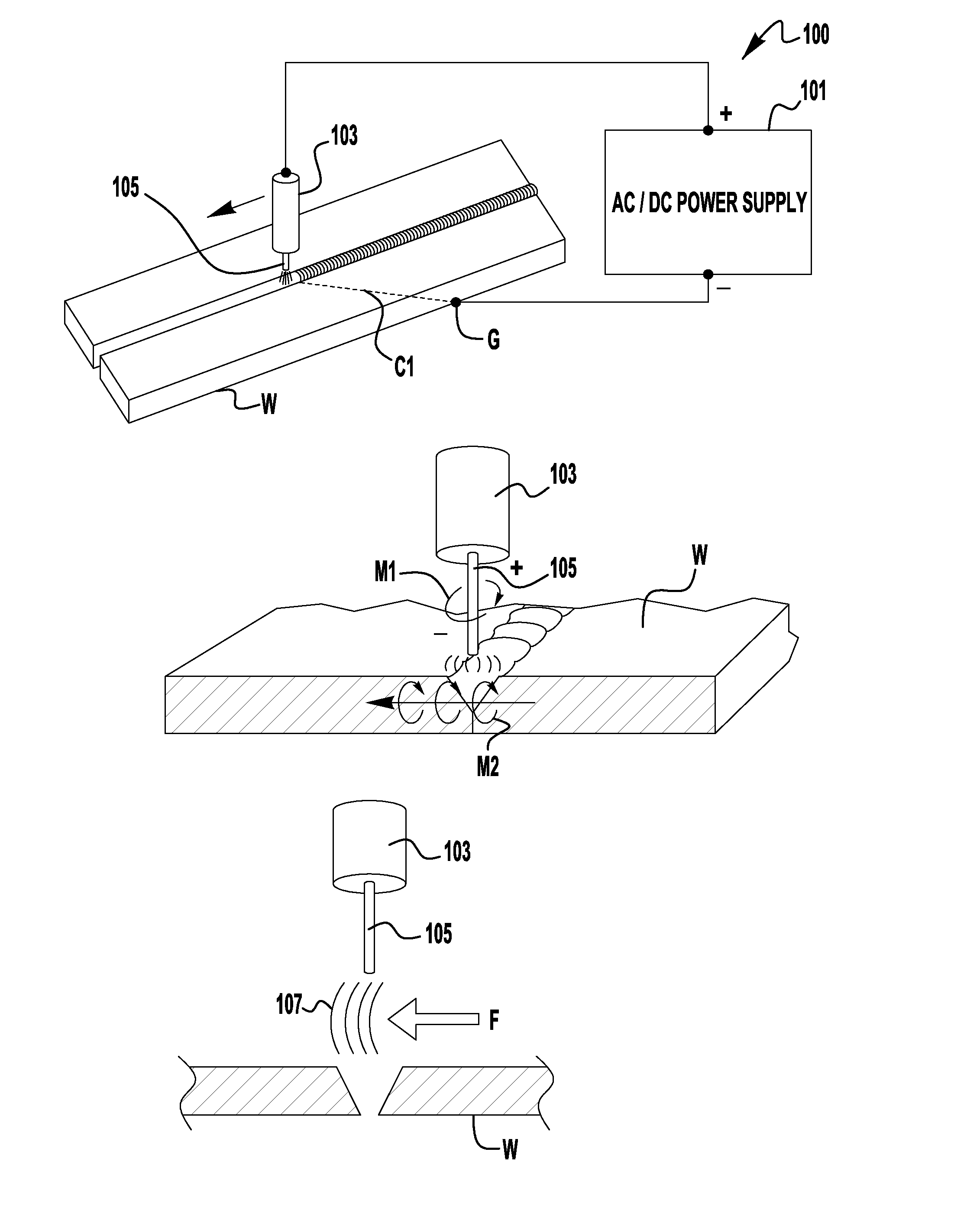
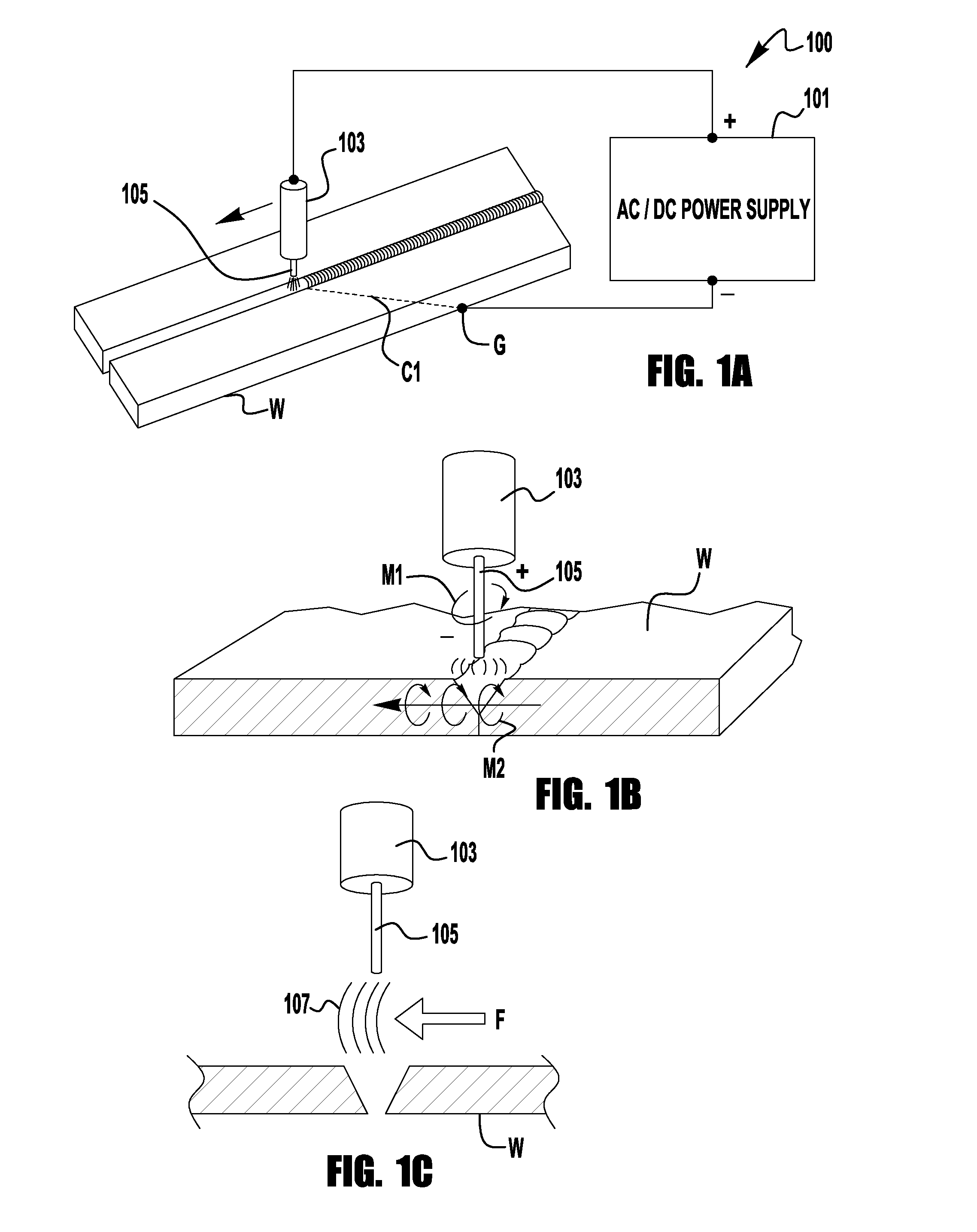
[0017]FIG. 1A depicts a welding system 100 with a single ground contact point G on the work piece. This is a typical welding system configuration in which a single ground contact lead couples a welding power supply 101 to the work piece W. The other contact lead couples the power supply 101 to a welding torch 103 which provides a welding current to a welding electrode 105, which may or may not be consumable. Thus, the power supply 101, torch 103, electrode 105, work piece W and the connecting leads create a welding circuit through which welding current flows. Because these components make up a welding circuit it is known that the work piece W provides a cu...


PUM

PropertyMeasurementUnit
angleaaaaaaaaaa
angleaaaaaaaaaa
currentaaaaaaaaaa

Abstract

A system and method of welding is provided where welding power supply has a first output electrically coupled to a welding electrode and a second output electrically coupled to a switching mechanism. The welding power supply provides a welding current through either of the first and second outputs to weld at least one work piece. The switching mechanism has at least a first and second switch position, where the first switch position is coupled to a first position on the at least one work piece and the second switch position is coupled to a second position on the at least one work piece, which is remote from the first position. During welding the switching mechanism switches between the first and second switch positions to change a current path for the welding current during through the at least one work piece.

Description

BACKGROUND OF THE INVENTION[0001]1. Field of the Invention[0002]Devices, systems, and methods consistent with the invention relate to welding, and more specifically related to work current switching to eliminate arc blow during welding.[0003]2. Description of the Related Art[0004]It is known that during welding a large current is passed from an electrode into a work piece to be welded, and this current can generate a relatively strong magnetic field. This magnetic field has a tendency to magnetize the work piece to be welded and / or the work piece fixtures. The magnetization of the work piece and / or the work piece fixture can cause the welding arc to deflect or bend from its ideal positioning which can tend to cause arc blow, or otherwise destabilize the welding arc. Furthermore, welding systems often use a single ground contact to the work piece. This creates a single current path through the work piece during welding. However, the use of a single current path throughout a welding o...

Claims


Application Information

Patent Timeline
Patent Type & Authority Applications(United States)
IPC IPC(8): B23K9/10
CPCB23K9/025B23K9/09B23K9/08
Inventor DANIEL, JOSEPH A.
Owner LINCOLN GLOBAL INC
Why Eureka
Try Eureka