
Mounting knuckle

Inactive Publication Date: 2013-09-05
U S T E INC DBA VISTA PROFESSIONAL OUTDOOR LIGHTING
View PDF7 Cites 2 Cited by
  • Summary
  • Abstract
  • Description
  • Claims
  • Application Information

AI Technical Summary

Benefits of technology

The present invention relates to grommets for knuckle joints. The grommet has an inner and an outer surface of rotation that fit together like a sphere, allowing infinite adjustability within the knuckle's range of motion. The grommet can be locked and unlocked over a specific segment of the knuckle, and it provides protection for the wiring when compressed. The technical effects of this invention are that it allows for precise and adjustable knuckle movement with minimal interference to the wiring, and it provides improved protection for the delicate knuckle components.

Problems solved by technology

Landscape lighting fixtures have traditionally been faced with significant challenges in precise aiming of such fixtures.
This challenge is compounded when water tightness is a requirement.
Conical tapers rely solely on friction to overcome rotational forces, but can become frozen in place.
Routing wiring through the single pivot knuckle assembly usually results in chafing of the wiring.
Because knuckles tend to be relatively small, tight spacing magnifies the chafing.
Shorting of the wring is commonplace in this area and is usually a mode of failure for this type of fixture.
Twisting of the wiring around the pivot point screw is another issue with electrical pass through routing.
Seals such as O-rings are often damaged or crushed as the fixture is adjusted.
The electrical penetration into the fixture housing must be done separately which adds another point of water entry and does not allow for clean second axis rotation.
Further, the electrical connections are accessible and, therefore, subject to exposure and vandalism.

Method used


Image

  • Mounting knuckle
  • Mounting knuckle
  • Mounting knuckle

Examples


Embodiment Construction

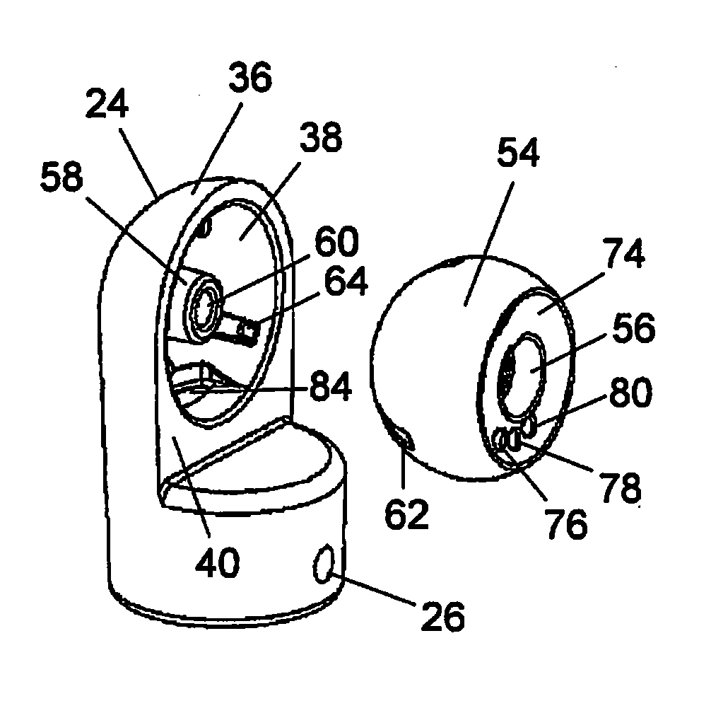
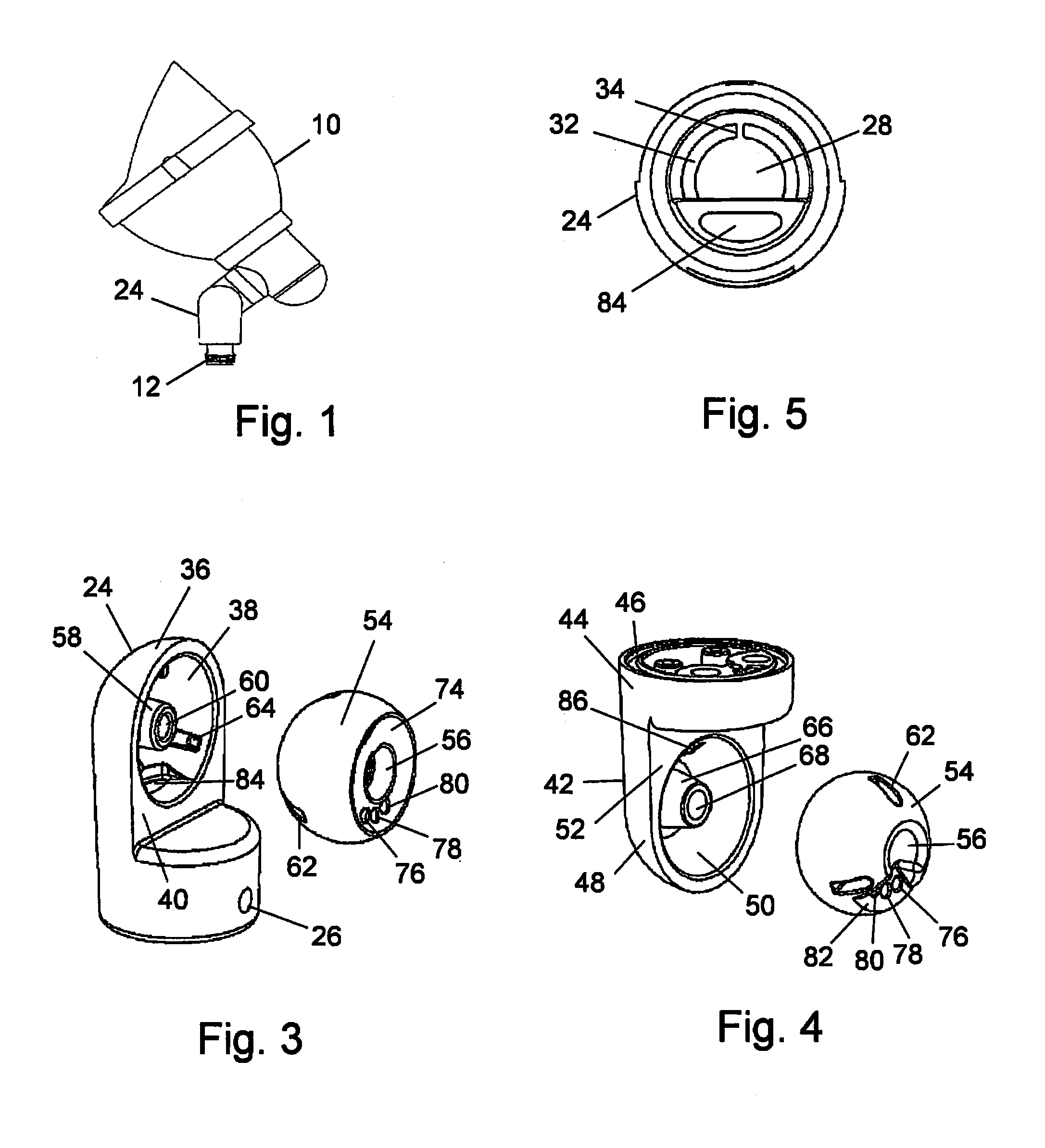
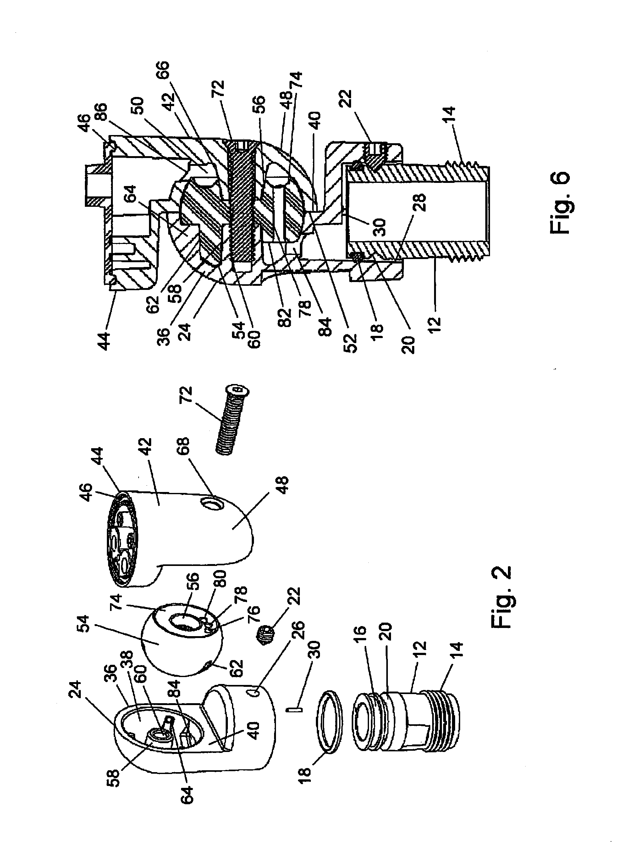
[0020]Turning in detail to the drawings, a knuckle for mounting electrical devices such as lamps 10 is disclosed. A knuckle mount 12 is shown to be substantially cylindrical with a passageway therethrough and threads 14 for engagement with an electrical connection supply box (not shown). The knuckle mount 12 typically extends with the axis therethrough in a vertical orientation to just above the ground in an outdoor environment. A seal groove 16 about the circumference of the mount 12 is sized to receive an O-ring seal 18. A locking groove 20 is arranged to receive a set screw 22 upon assembly.

[0021]A first knuckle element 24 is rotatably mounted on the knuckle mount 12. The set screw 22 is threaded into the locking groove 20 through a threaded hole 26. The set screw 22 may be placed to simply retain the knuckle element 24 from separating from the knuckle mount 12 or be tightened to restrain the knuckle element 24 from rotating on the knuckle mount 12. The O-ring seal 18 is sized to...


PUM


Abstract

A knuckle assembly for mounting an electrical device includes a rotatable knuckle mount, an articulated knuckle and an electrical device mount. Two knuckle elements forming the articulated knuckle each include an open cavity, which together form a closed cavity. One of the knuckle elements is pivotally attached to the rotatable knuckle mount and the other includes the electrical device mount. A grommet is positioned in the closed cavity; and a fastener engages the knuckle elements and extends through the grommet. The grommet includes spherical or spheroidal segments complementary to the inner surfaces of the closed cavity and in interfering fit when assembled. The grommet is in non-rotational engagement with one of the knuckle elements. Wires extend through the grommet adjacent a central through hole. A fastener extending through the central through hole draws the knuckle elements together to fix the grommet and seal the assembly.

Description

[0001]This application claims priority based on Provisional Application 61 / 605,708, filed Mar. 1, 2012, the disclosure of which is incorporated by reference in its entirety.BACKGROUND OF THE INVENTION[0002]The field of the present invention is adjustable mounts for electrical devices.[0003]Landscape lighting fixtures have traditionally been faced with significant challenges in precise aiming of such fixtures. Adjustment devices used to aim the fixtures must endure the rigors of being mounted in the ground where abuses from maintenance, fertilizer, water, mud, debris, vandalism, and weather extremes are commonplace. Furthermore, the mechanisms commonly are asked to articulate in multiple axes, along with being capable of routing electrical wires through the articulation. This challenge is compounded when water tightness is a requirement.[0004]Existing mechanisms used to mount, adjust and aim these types of fixtures include knuckle joint assemblies and yoke or stirrup assemblies. Knuc...

Claims


Application Information

Patent Timeline
IPC IPC(8): H05K7/00
CPCF21V21/26F21V21/30F16M11/10Y10T403/32213F16M13/02Y10T403/32311Y10T403/32565F16M11/2014
Inventor LEONHARDT, MICHAEL P.TYSON, GLENN M.
Owner U S T E INC DBA VISTA PROFESSIONAL OUTDOOR LIGHTING
Learn More