Light-emitting device assembly and lighting device

Inactive Publication Date: 2013-09-05
NITTO DENKO CORP
View PDF4 Cites 0 Cited by
  • Summary
  • Abstract
  • Description
  • Claims
  • Application Information

AI Technical Summary

Benefits of technology

[0030]Such a lighting device can be produced from the above-described li

Problems solved by technology

Thus, there are limitations

Method used


Image

  • Light-emitting device assembly and lighting device
  • Light-emitting device assembly and lighting device
  • Light-emitting device assembly and lighting device

Examples


Embodiment Construction

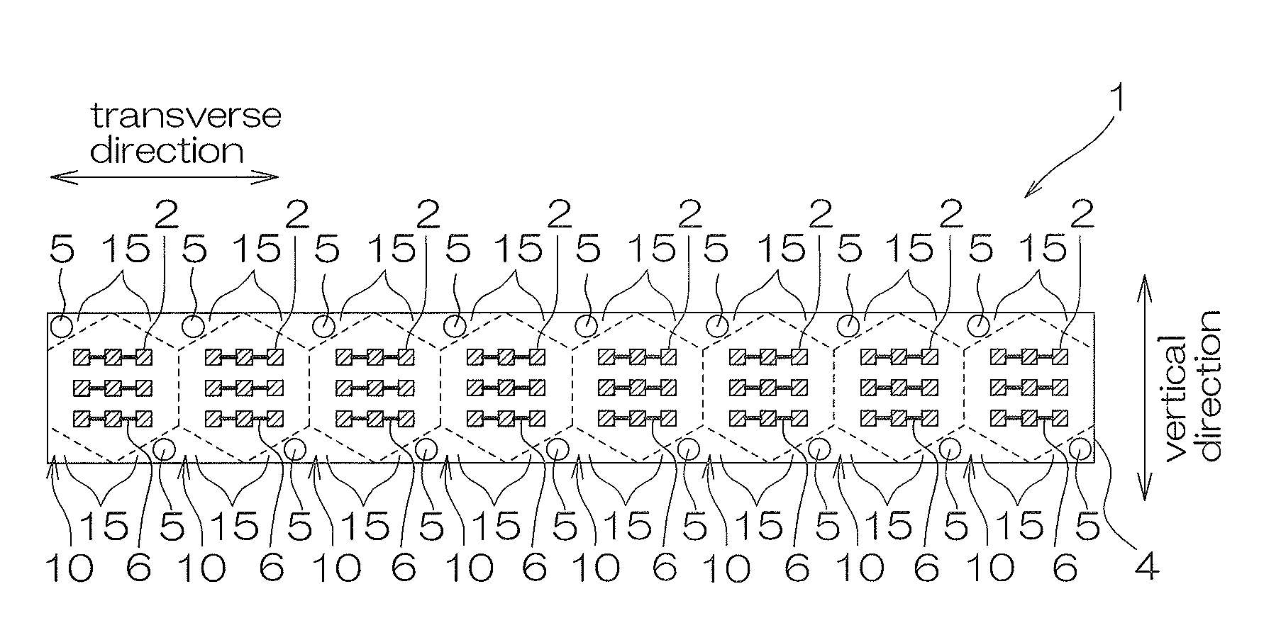
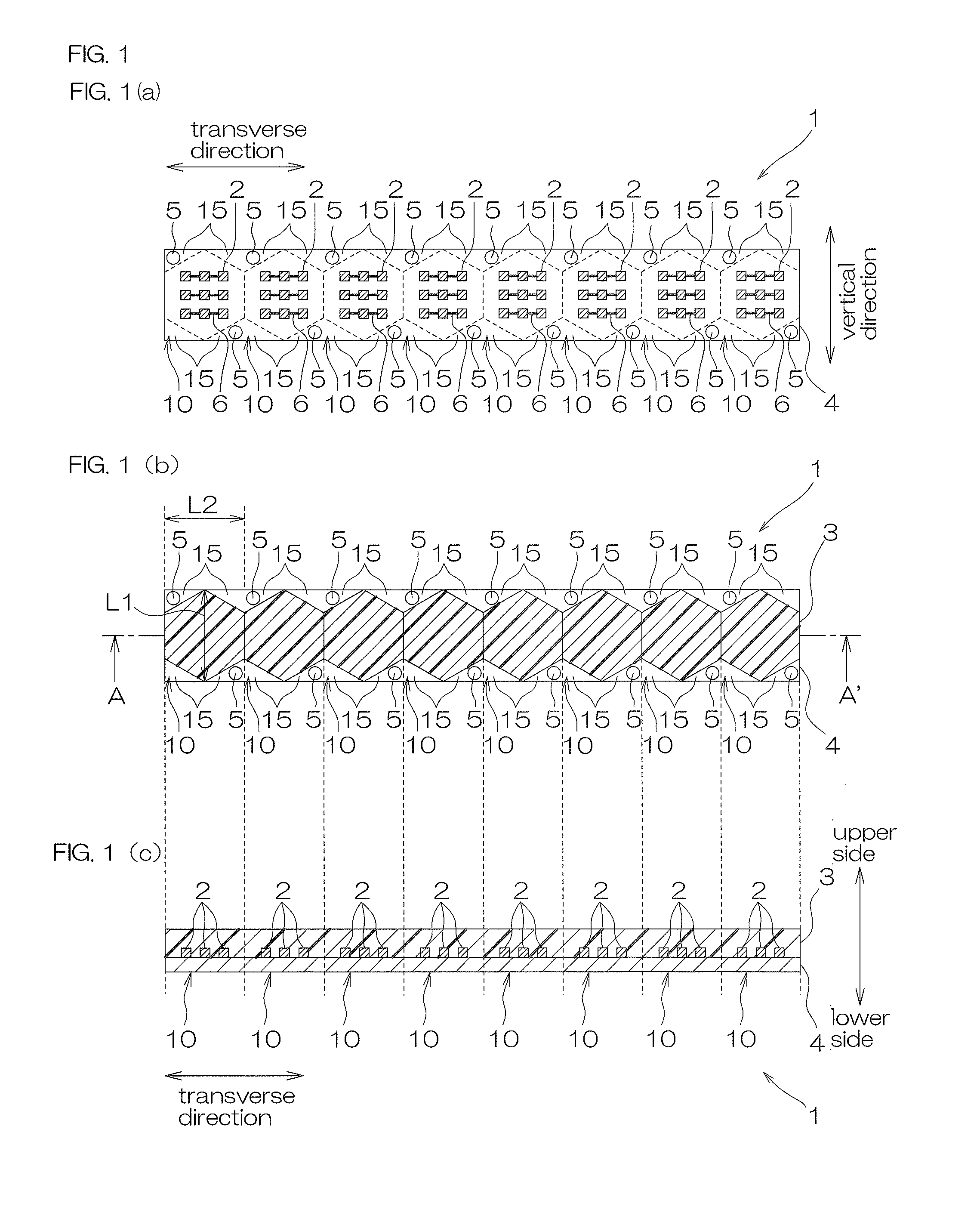
[0050]FIG. 1 shows a schematic diagram of an embodiment (embodiment in which the encapsulating layer is formed into a generally regular hexagonal shape when viewed from the top) of the light-emitting device assembly of the present invention; FIG. 1 (a) illustrating a plan view before encapsulation by the encapsulating layer, FIG. 1 (b) illustrating a plan view after encapsulation by the encapsulating layer, and FIG. 1 (c) illustrating a cross-sectional view taken along line A-A′ in FIG. 1 (b).

[0051]In FIG. 1 (a), the position at which an encapsulating layer 3 described later is disposed is shown by broken line, and in FIG. 1 (b) and FIG. 1 (c), a wire 6 described later is omitted.

[0052]In FIG. 1, a light-emitting device assembly 1 is formed by integral continuation of a plurality of (e.g., eight) light-emitting devices 10.

[0053]In the description below, directions mentioned are based on the case where the light-emitting device assembly 1 is placed horizontally; up-down direction on ...


PUM


Abstract

A light-emitting device assembly includes a plurality of light-emitting devices. The plurality of light-emitting devices each includes a circuit board including a pair of electrodes to be connected to an external power source, and to which an electric power is supplied from the power source through the electrodes; a semiconductor element supported on and electrically connected to the circuit board; and an encapsulating layer that encapsulates the semiconductor element on the circuit board. The plurality of light-emitting devices are disposed so as to be continuous in one direction. The encapsulating layer is disposed so that the encapsulating layers of the light-emitting devices next to each other are in contact with each other when viewed from the top.

Description

CROSS-REFERENCE TO RELATED APPLICATION[0001]The present application claims priority from Japanese Patent Application No. 2012-046876 filed on Mar. 2, 2012 and Japanese Patent Application No. 2012-158620 filed on Jul. 17, 2012, the contents of which are hereby incorporated by reference into this application.BACKGROUND OF THE INVENTION[0002]1. Field of the Invention[0003]The present invention relates to a light-emitting device assembly and a lighting device, in particular to a light-emitting device assembly in which a plurality of light-emitting devices are disposed continuously in one direction, and a lighting device produced by using the light-emitting device assembly.[0004]2. Description of Related Art[0005]It has been known that light-emitting diode devices are produced by disposing a single or a plurality of light-emitting diode (LED) elements on a substrate, and encapsulating the LED elements with an encapsulating resin layer.[0006]To be specific, for example, Japanese Unexamin...

Claims


Application Information

Patent Timeline
IPC IPC(8): F21V21/00
CPCF21V21/00H01L25/0753H01L33/54H01L2933/005H01L2924/0002H01L2924/00
Inventor OOYABU, YASUNARIKATAYAMA, HIROYUKIUMETANI, SHIGEHIROITO, HISATAKAWAKIYA, SHINSUKE
Owner NITTO DENKO CORP
Why Eureka
Try Eureka