Retainer for sliding device provided with buffer member

Active Publication Date: 2013-09-05
SEGOS
View PDF14 Cites 16 Cited by
  • Summary
  • Abstract
  • Description
  • Claims
  • Application Information

AI Technical Summary

Benefits of technology

The present invention provides a retainer with a buffer member that can minimize noise and prevent damage caused by pulling-out impact, thus increasing the longevity of the retainer. The buffer member is fixed to the retainer and can be assembled and disassembled by the user, improving the reliability of the arrangement. The buffer member is made of a soft material that improves buffering force and can repeatedly carry out its function. The retainer is made of a rigid synthetic resin material that maintains the strength of its rolling members, while the buffer members are made of a soft synthetic resin material that improves anti-noise and buffering performance. The retainer and buffer members can be integrated injection-molded, improving the efficiency of molding.

Problems solved by technology

At this time, noise is produced to due to impact, which is problematic.

Method used


Image

  • Retainer for sliding device provided with buffer member
  • Retainer for sliding device provided with buffer member
  • Retainer for sliding device provided with buffer member

Examples


first embodiment

[0048]Reference will be made to a retainer for a sliding device provided with a buffer member according to the present invention with reference to FIG. 1 to FIG. 5.

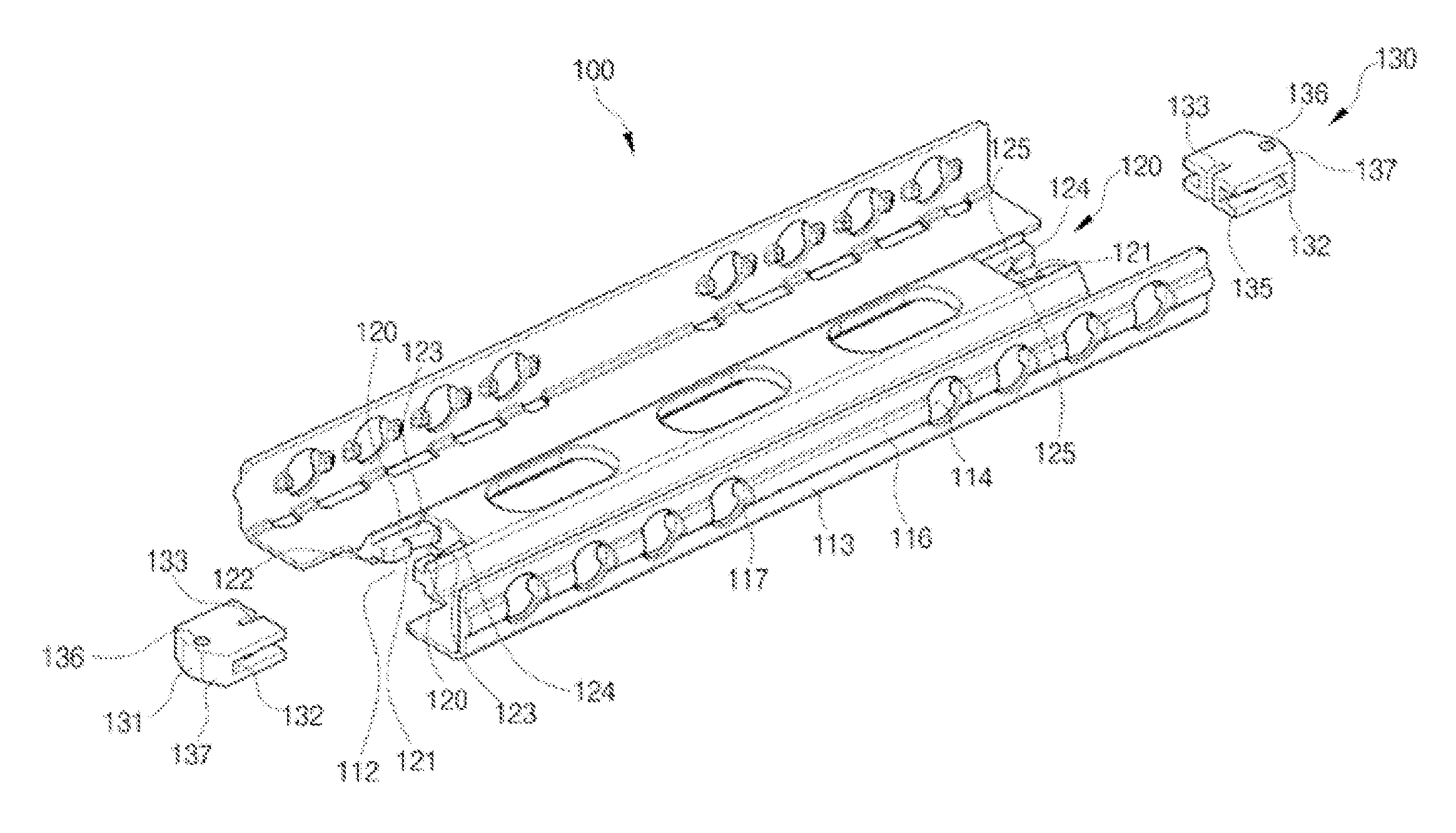
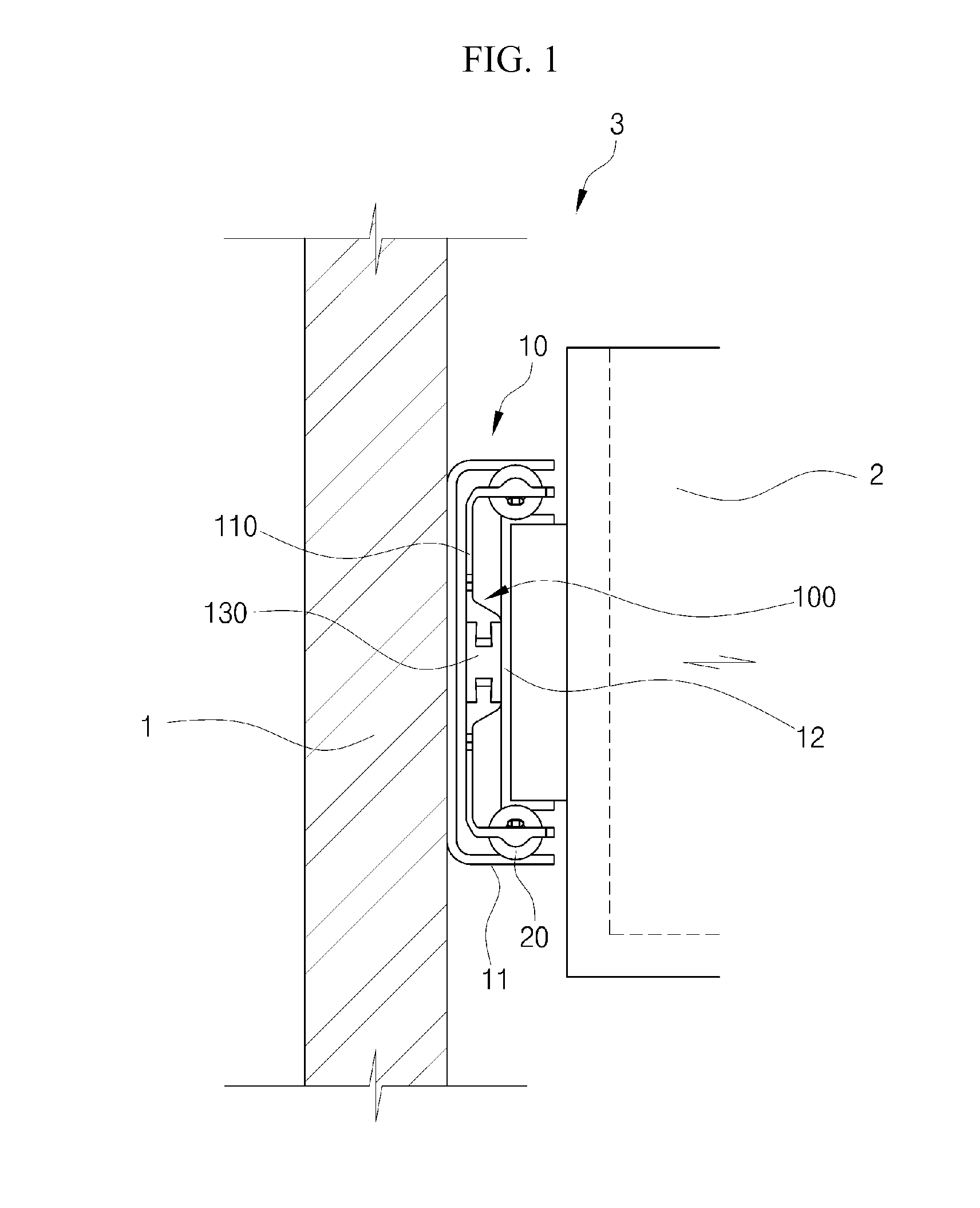
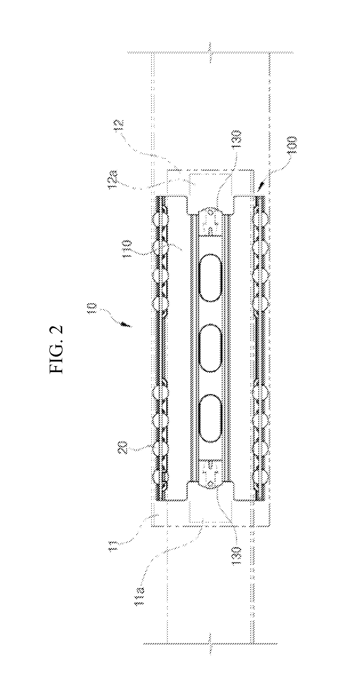
[0049]FIG. 1 a configuration view showing the state in which the retainer for a sliding device provided with a buffer member according to the first embodiment of the present invention is assembled to the sliding device, which is provided in a body and a receptacle, FIG. 2 is a configuration view showing the operating state of the sliding device to which the retainer for a sliding device provided with a buffer member is assembled, FIG. 3 is an exploded perspective view showing the retainer for a sliding device provided with a buffer member according to the first embodiment of the present invention, FIG. 4 is an exploded front elevation view showing the retainer for a sliding device provided with a buffer member shown in FIG. 3, and FIG. 5 is a front elevation view showing the assembly state of the retainer for a sliding de...

second embodiment

[0071]In addition, reference will be made to a retainer for a sliding device provided with a buffer member according to the present invention with reference to FIG. 6 to FIG. 8.

[0072]FIG. 6 is an exploded perspective view showing the retainer for a sliding device provided with a buffer member according to the second embodiment of the present invention, FIG. 7 is an exploded front elevation view showing the retainer for a sliding device provided with a buffer member shown in FIG. 6, and FIG. 8 is a front elevation view showing the assembly state of the retainer for a sliding device provided with a buffer member shown in FIG. 6.

[0073]Referring to FIGS. 6 to 8, the retainer 100 for a sliding device provided with a buffer member according to a second embodiment of the present invention includes a body part 110, buffering protrusion parts 200 and second buffer members 210. Here, a description of the body 110 will be omitted since its configuration is identical with the corresponding comp...

third embodiment

[0082]In addition, reference will be made to a retainer for a sliding device provided with a buffer member according to the present invention with reference to FIG. 9 to FIG. 11.

[0083]FIG. 9 is an exploded perspective view showing the retainer for a sliding device provided with a buffer member according to the third embodiment of the present invention, FIG. 10 is an exploded front elevation view showing the retainer for a sliding device provided with a buffer member shown in FIG. 9, and FIG. 11 is a front elevation view the assembly state of the retainer for a sliding device provided with a buffer member shown in FIG. 9.

[0084]Referring to FIG. 9 to FIG. 11, the retainer 100 for a sliding device provided with a buffer member according to a third embodiment of the present invention includes a body part 110, buffering fixing parts 300 and third buffer members 310. Here, a description of the body 110 will be omitted since its configuration is identical with the corresponding component o...


PUM


Abstract

A retainer for a sliding device provided with a buffer member includes a body which is arranged between sliding rails, and has buffering insertion grooves on one side that are open in the outward direction, which is the withdrawal direction, and on the other side, which is the closing direction, so as to adjust the range of withdrawal when the sliding rails are withdrawn; and buffer member portions protruding from the two ends of the body, respectively, in the direction of an accommodation body, and being arranged so as to be respectively inserted into the buffering insertion grooves for coming into contact when the sliding rails are withdrawn.

Description

TECHNICAL FIELD [0001]The present invention relates to a retainer for a sliding device provided with a buffer member.BACKGROUND ART [0002]In general, a piece of furniture, such as a desk or closet, or a home appliance, such as a refrigerator, a washing machine or a microwave oven, is provided with a receptacle which is pushed in and pulled out in a state in which an object is contained therein. A body of the furniture or home appliance has an accommodating space, and the receptacle having an inner space in which the object is contained is slidably coupled via a sliding device, which is disposed on both sides thereof, such that it can slide into and out of the accommodating space.[0003]A typical sliding device is disposed between the body and the receptacle, in which a rail fixed to the body and a rail which moves along with the receptacle are disposed such that they overlap each other. Rolling means such as balls or rollers are disposed between the overlapping rails such that the fi...

Claims


Application Information

Patent Timeline
IPC IPC(8): A47B88/04
CPCA47B88/04A47B2210/0097A47B2210/0029A47B2210/0018A47B88/477A47B88/40
Inventor PARK, YOON SIKKIM, JAE WON
Owner SEGOS
Why Eureka
Try Eureka