Unlock instant, AI-driven research and patent intelligence for your innovation.

Cooling structure of electronic device

a technology of electronic devices and cooling structures, which is applied in the direction of supporting structure mounting, casings/cabinets/drawers, and casings/cabinets/drawers details of electrical appliances, etc., can solve the problems of reducing the cooling effect of power source units, reducing the total weight of electronic devices, and demonstrating good cooling effects, etc., to achieve simple cooling structures and high cooling effects. , the effect of simple structur

Active Publication Date: 2013-09-05
NEC ASIA PACIFIC PTE LTD
View PDF4 Cites 7 Cited by
  • Summary
  • Abstract
  • Description
  • Claims
  • Application Information

AI Technical Summary

Benefits of technology

The invention provides a simple cooling structure for an electronic device that effectively cools the power source units supplying electric power to CPUs. The power source units are placed in a downstream position to the cooling air generated by multiple fans inside the housing. The power source units are also positioned in a separate area from the electronic parts, without overlapping with them in the cooling airflow direction. These features improve the cooling effect for the power source units, which are the main heat sources in the device.

Problems solved by technology

However, the technology of Patent Literature 1 is disadvantageous because of its complex structure owing to the formation of air passages differently for each logic unit and each power source unit, which may increase the total weight of an electronic device.
However, the technology of Patent Literature 2 may not demonstrate a good cooling effect when one power source additionally applies its heat to the other power source, thus totally increasing heat produced by a pair of power sources vertically combined together.
This may further degrade a cooling effect for the power source units 105.
This may increase the cost price of the server 100.
Moreover, this may entail unnecessary limitation to the size and capacity of the server 100 so as to prevent an increase in a heating value of each power source unit 105

Method used


Image

  • Cooling structure of electronic device
  • Cooling structure of electronic device
  • Cooling structure of electronic device

Examples


first embodiment

1. First Embodiment

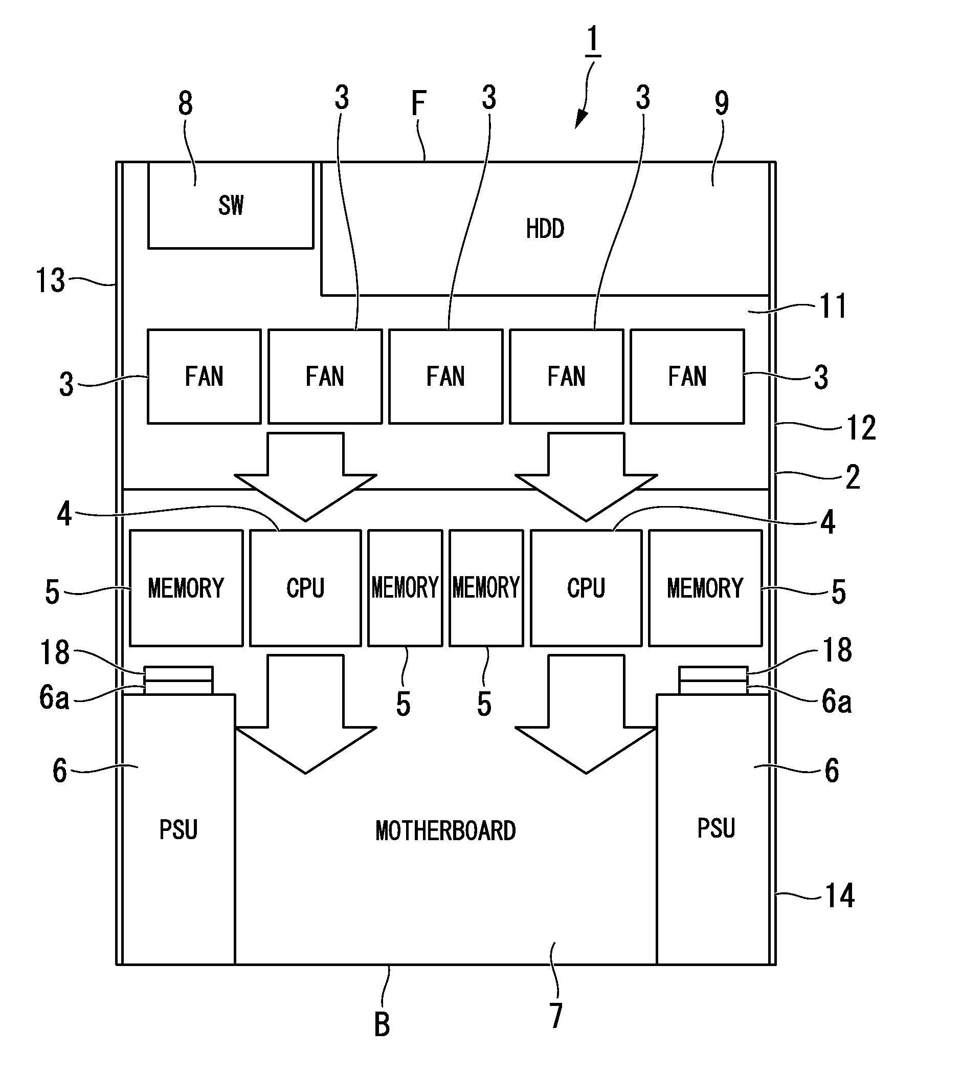
[0025]An electronic device (i.e. a server) 1 according to a first embodiment of the present invention will be described with reference to FIGS. 1 to 4. FIG. 1 is a plan view of the server 1 partly in cross section; FIG. 2 is a rear view of the server 1; and FIG. 3 is a perspective view showing a power box installed in the server 1.

[0026]The server 1 includes a housing 2, five fans 3, two CPUs 4 (i.e. electronic parts serving as heat sources), four memories 5, two power source units (or power supply units: PSU) 6, a motherboard 7, a switching device (SW) 8, and a hard disk drive (HDD serving as an auxiliary storage device) 9. Herein, each CPU 4 is accompanied with a pair of memories 5 on the left and right sides thereof In FIG. 1, a reference sign F denotes a front face of the server 1, while a reference sign B denotes a back face (or a rear face) of the server 1.

[0027]As shown in FIG. 2, the housing 2 includes a main frame 14 and a cover 15. The main frame 14 incl...

second embodiment

2. Second Embodiment

[0047]Next, an electronic device 40 according to a second embodiment of the present invention will be described with reference to FIG. 5. The electronic device 40 is configured using a housing 41 having a front face F and a back face (or a rear face) B. The electronic device 40 includes a plurality of fans 42, a pair of electronic parts 43 serving as heat sources, and a pair of power source devices 44, all of which are arranged inside the housing 41. The fans 42 cause cooling air to propagate from the front face F to the rear face B in the housing 41. The electronic parts 43 are positioned in the downstream side of cooling air produced by the fans 42. One of the power source units 44 may solely produce adequate electric power to drive the electronic device 40. The power source units 44 are arranged in the downstream side compared to the electronic parts 43. The power source units 44 are spaced from each other in the direction perpendicular to the cooling airflow ...


PUM


Abstract

A cooling structure is designed for an electronic device including a plurality of fans causing cooling air, a plurality of electronic parts serving as heat sources, and a plurality of power source units, all of which are arranged inside the housing. The electronic parts are positioned in the downstream side of cooling air produced by the fans, while the power source units are positioned in the further downstream side of cooling air compared to the electronic parts. The power source units are spaced out from each other in the perpendicular direction to the cooling airflow direction of cooling air such that the power source units do not overlap with the electronic parts in the cooling airflow direction in plan view. The cooling structure prevents cooling air, which is temporarily warmed by the electronic parts, from directly flowing into the power source units, thus improving a cooling effect.

Description

BACKGROUND OF THE INVENTION[0001]1. Field of the Invention[0002]The present invention relates to a cooling structure of an electronic device such as a server, a host computer, and an industrial computer each equipped with a motherboard, a power source, and a cooling fan.[0003]The present application claims priority on Japanese Patent Application No. 2012-48062, the content of which is incorporated herein by reference.[0004]2. Description of the Related Art[0005]Conventionally, electronic devices including power sources and electronic parts, serving as heat sources, need to be equipped with cooling fans for cooling heat sources. It is important for electronic devices, each including a plurality of electronic parts and a plurality of power sources (or power source units), to achieve a cooling structure for efficiently cooling heat sources.[0006]Various technologies regarding cooling structures of electronic devices have been developed and disclosed in various documents. For example, P...

Claims


Application Information

Patent Timeline
IPC IPC(8): H05K5/02
CPCH05K5/0213H05K7/20145H05K7/1492H05K7/20727
Inventor NAGASAKA, YORITO
Owner NEC ASIA PACIFIC PTE LTD