Battery assembly

a battery and assembly technology, applied in secondary cells, electrical equipment, cell structural combinations, etc., can solve the problems of insufficient ratio of normal battery cells and insufficient reflection of high temperature of battery cells, and achieve the effect of simple cooling structure and extended battery system li

Inactive Publication Date: 2013-01-03
MITSUBISHI HEAVY IND LTD
View PDF4 Cites 7 Cited by
  • Summary
  • Abstract
  • Description
  • Claims
  • Application Information

AI Technical Summary

Benefits of technology

[0015]According to the battery system of the present invention, the lifetime of the battery system can be extended, since the variation of the degradation speed of the battery cells in the arm can be reduced and the degradation speed of the battery cells can be averaged with a simple cooling structure.

Problems solved by technology

Consequently, even when the temperature of a part of the battery cells constituting a certain arm is higher than the temperature of the other battery cell, there is a possibility that the temperature of the battery cell with a high temperature can not be sufficiently reflected as the temperature of the arm when the transfer of heat to a temperature measurement point installed inside a battery case is slow or the ratio of the normal battery cells is sufficiently large.

Method used


Image

  • Battery assembly
  • Battery assembly
  • Battery assembly

Examples


first embodiment

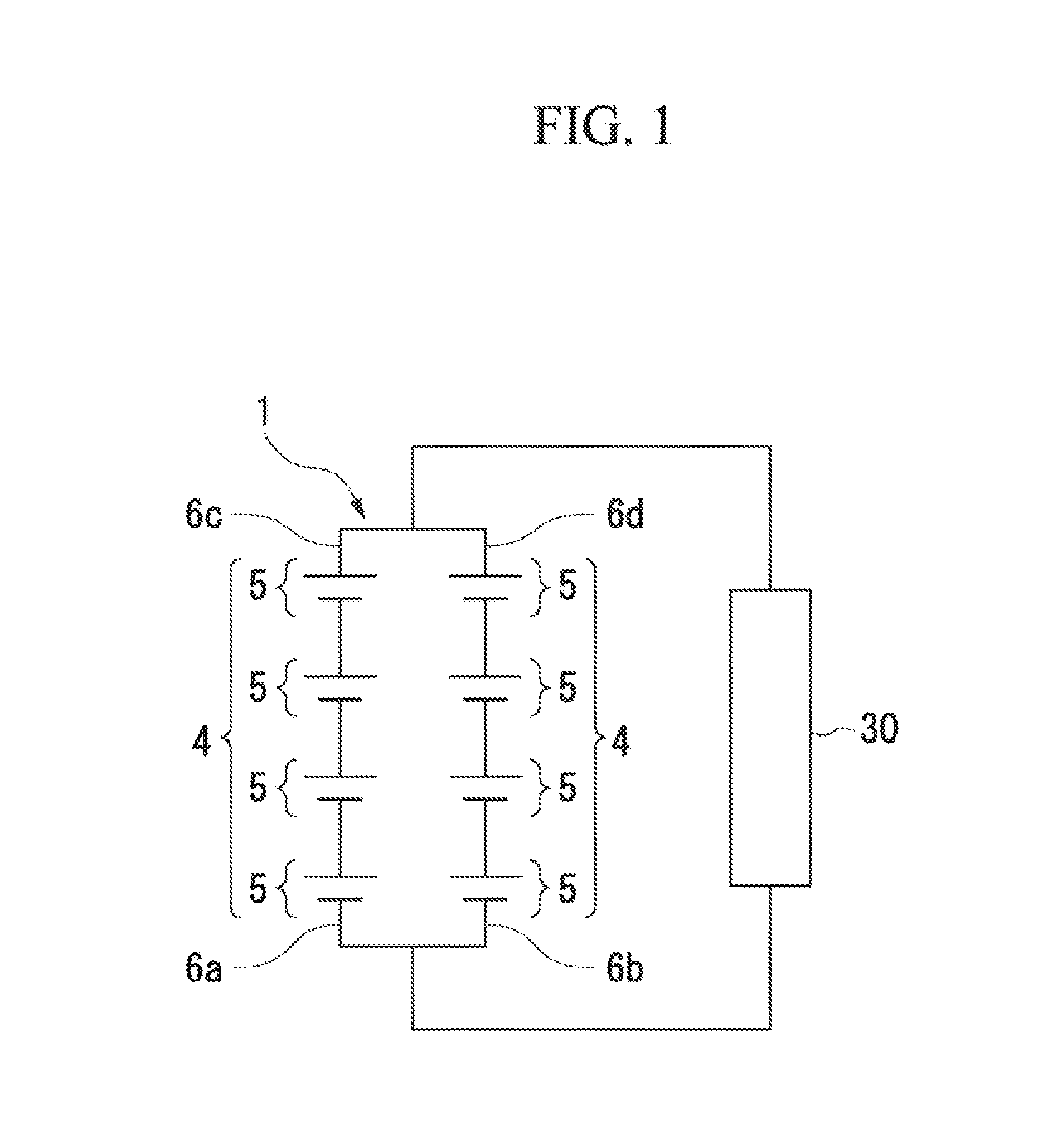
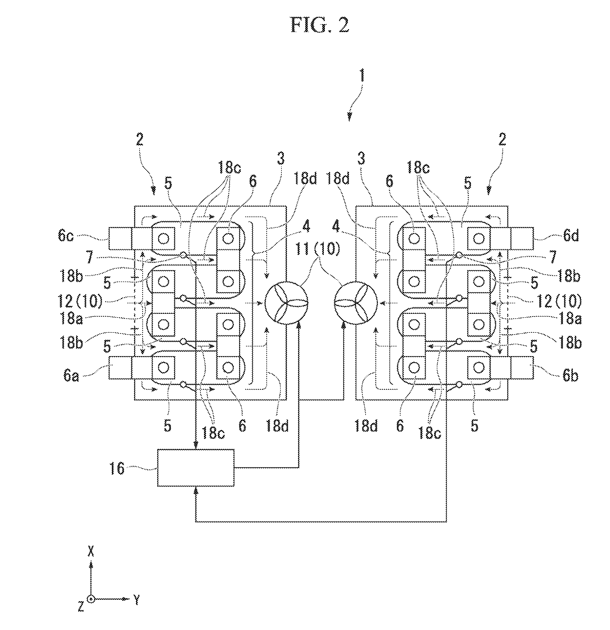
[0023]FIG. 1 is a connection example of an battery system according to a first embodiment of the present invention. FIG. 2 is a configuration diagram of the battery system 1 shown in FIG. 1. FIG. 3 is a diagram illustrating a correlation between a degradation rate and a temperature of a common battery. In the embodiment, an example of the battery system with a plurality of battery units 2 will be described. However, the battery system described in the present invention may include one or more battery units 2.

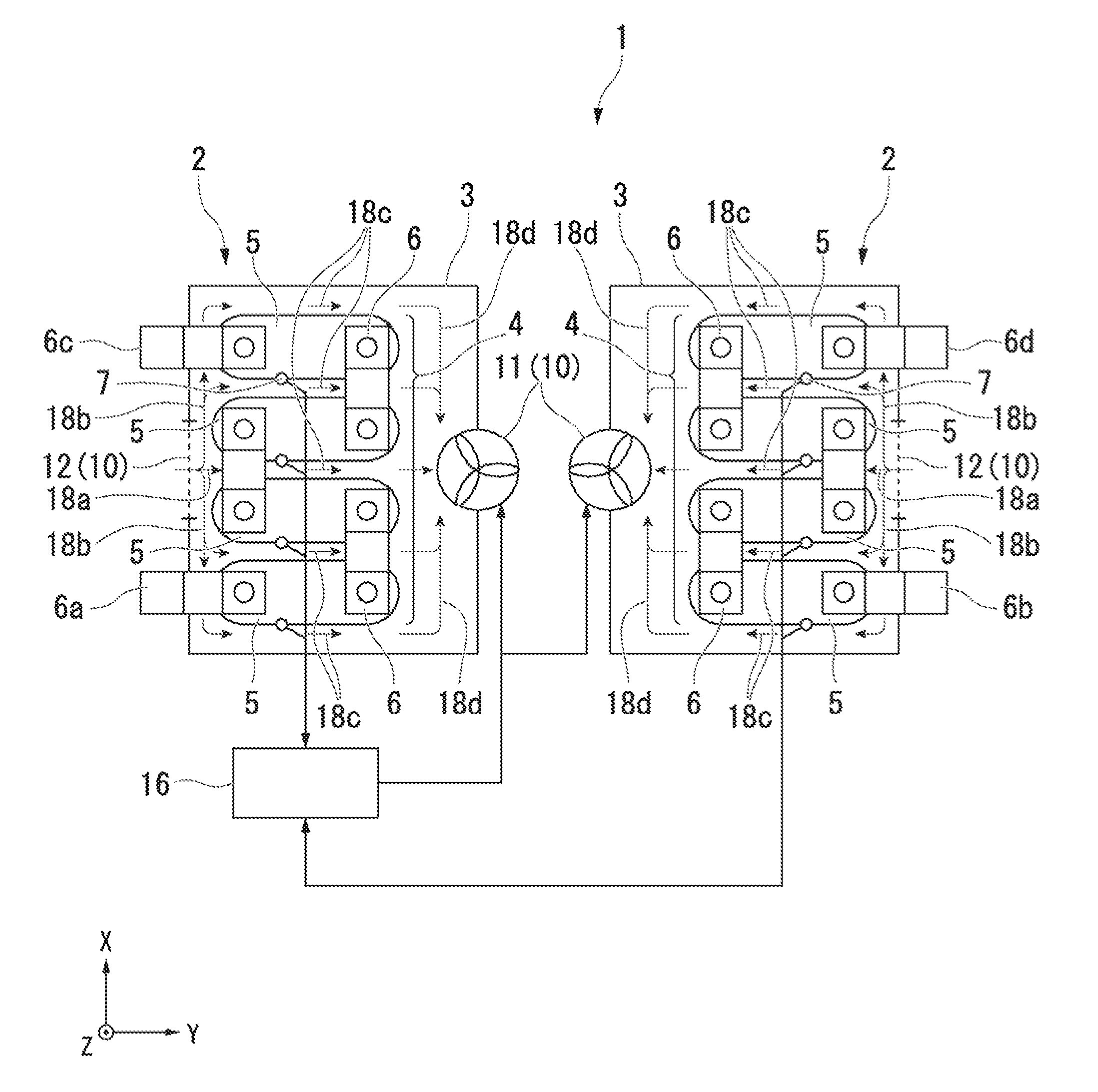
[0024]As shown in FIGS. 1 and 2, the battery system 1 of the embodiment includes two battery units 2. Each battery unit 2 includes: a plurality of arms 4 which are formed by electrically connected respective battery cells 5 in series to each other through a bulbar 6; a plurality of battery cases 3 which are provided so as to accommodate each of corresponding arm 4; and a plurality of cooling units 10 which are provided to each of battery cases 3. Further, the battery system 1 is...

second embodiment

[0043]FIG. 4 is a connection example of an battery system according to a second embodiment of the present invention. Further, FIG. 5 is a configuration diagram of the battery system 1 shown in FIG. 4. As shown in FIGS. 4 and 5, the battery system 1 of the embodiment includes one or more battery units 2. The battery unit 2 includes: two arms 4 which are formed by electrically connected the plurality of battery cells 5 in series to each other through the busbar 6; the battery case 3 which accommodates the arm 4; and the cooling unit 10 which is provided to the battery case 3.

[0044]In the embodiment, the arms 4 are electrically connected in series to each other so that the busbars 6b and 6c with different polarities are connected to each other. Further, in the embodiment, the cooling unit 10 includes the fan 11 which exhausts the air inside the battery case 3 to the outside; the intake exhaust port 12 which feeds and exhausts the air between the inside and the outside of the battery ca...

modified example

[0057]The technical scope of the present invention is not limited to the above-described embodiments, and the respective embodiments may be appropriately combined with each other. That is, various modifications may be made without departing from the spirit of the invention. Hereinafter, a modified example of the embodiment is illustrated. FIG. 6 is a diagram illustrating the modified example according to the first embodiment. In FIG. 6, the same reference numerals are applied to the same configuration as that of the first embodiment, and the description thereof will be appropriately omitted. The modified example and the first embodiment are different from each other in the position and the number of the intake exhaust ports.

[0058]In the first embodiment, one intake exhaust port 12 is provided for each battery unit 2, but in the modified example, the intake exhaust ports 17 are provided in numbers equal to the number of passageways 18c. More specifically, as shown in FIG. 6, five pas...


PUM

PropertyMeasurementUnit
arbitrary angleaaaaaaaaaa
temperatureaaaaaaaaaa

Abstract

According to the invention, an battery system with an arm formed by electrically connected a plurality of battery cells to each other is provided. The battery system includes: a temperature detection unit that is provided to each of battery cells; a cooling unit that cools the arm; and a control unit that identifies a maximum value from the temperatures of the battery cells measured by the temperature detection unit and controls the cooling unit so that the maximum value falls within a predetermined allowable temperature range.

Description

TECHNICAL FIELD[0001]The present invention relates to an battery system which includes a cooling system. In the battery system, multiple arms are electrically connected each other. In the arm, multiple battery cells are connected in series to each other.[0002]Priority is claimed on Japanese Patent Application No. 2010-057921, filed Mar. 15, 2010, the content of which is incorporated herein by reference.BACKGROUND ART[0003]Conventionally, as a method of cooling an battery system which consists of electrically connected (hereinafter, referred to as “electrical connection”) a plurality of blocks (arms), having a plurality of battery cells connected in series to each other, in series or in parallel to each other in combination, a method, in which cooling of each arm is controlled so that a difference in the temperature between the arms does not exceed a threshold value, has been adopted (for example, PTL 1). Accordingly, the lifetime of the entire battery system can be improved by reduc...

Claims


Application Information

Patent Timeline
Patent Type & Authority Applications(United States)
IPC IPC(8): H01M10/50H01M10/48H01M10/60H01M10/613H01M10/617H01M10/633H01M10/637H01M10/6557H01M10/6563
CPCH01M10/5004H01M10/502H01M10/5038H01M10/425H01M10/486H01M10/5008H01M10/5067H01M10/63H01M10/6563H01M10/652H01M10/617H01M10/613Y02E60/10
Inventor NISHIDA, TAKEHIKO
Owner MITSUBISHI HEAVY IND LTD
Why Eureka
Try Eureka