
Differential pressure sensor

a pressure sensor and differential technology, applied in the direction of fluid pressure measurement by mechanical elements, fluid pressure measurement using elastically deformable gauges, instruments, etc., can solve problems such as delaminate bonded parts, and achieve the effects of buffering pressure forces and thermal stresses, reducing part counts, and reducing siz

Inactive Publication Date: 2013-09-12
YAMATAKE HONEYWELL CO LTD
View PDF13 Cites 21 Cited by
  • Summary
  • Abstract
  • Description
  • Claims
  • Application Information

AI Technical Summary

Benefits of technology

The present invention relates to a differential pressure sensor that can prevent delamination of the sensor chip caused by high pressure or changes in the ambient temperature. This is achieved through an elastic holding member which buffers the pressure forces and thermal stresses that act on the bonded portions of the sensor chip. Additionally, the sensor chip is held under pressure between two duct members, which further enhances the stability of the sensor. The elastic holding member may, for example, be made of elastic first and second connecting ducts or leaf springs. The technical effect of this invention is to improve the reliability and reliability of differential pressure sensors in various industrial applications.

Problems solved by technology

However, satisfying such demands enlarges the pressure bearing surface internally, causing the application of pressures that are large enough to break the bonded portions within the sensor chip 11.
In this case, when there is a high pressure there is the risk that large pressure forces will act on the bonded portions in this five-layer structure, causing the bonded portions to delaminate.

Method used


Image

  • Differential pressure sensor
  • Differential pressure sensor
  • Differential pressure sensor

Examples


Embodiment Construction

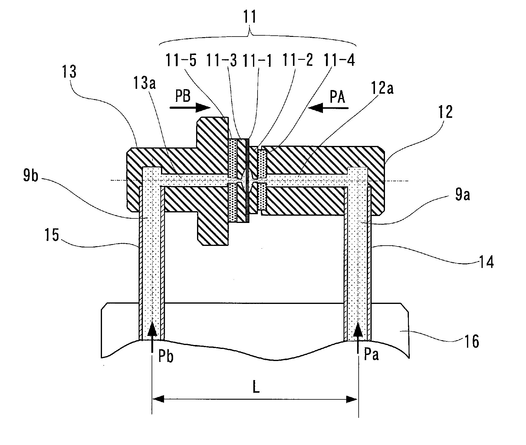
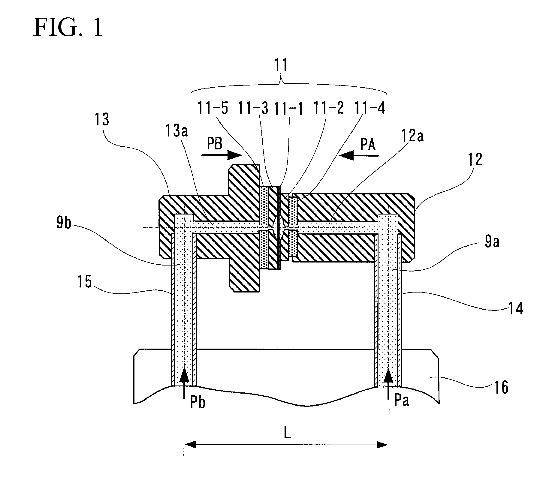
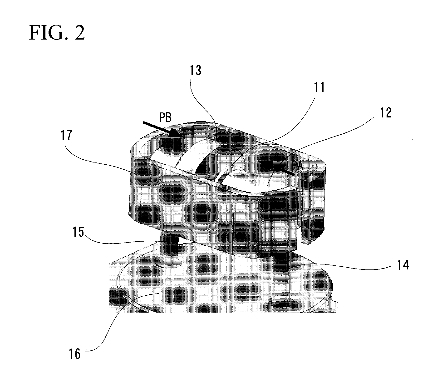
[0029]A form of example according to the present invention will be explained below in detail, based on the drawings. FIG. 1 is a diagram illustrating the critical portions in an example of a differential pressure sensor according to the present invention. In this figure, a supporting structure for the sensor chip 11 (FIG. 6) that is incorporated in a meter body is illustrated as the structure for the differential pressure sensor that is incorporated in the differential pressure transmitter.

[0030]In this supporting structure, a first duct member 12 is bonded to one face of the sensor chip 11, and a second duct member 13 is bonded to the other face of the sensor chip 11. The first duct member 12 has, therein, a pressure guiding duct 12a that guides the measurement pressure Pa to the one face of the sensor diaphragm 11-1 and the second duct member 13 has, therein, a pressure guiding duct 13a for guiding the measurement pressure Pb to the other face of the sensor diaphragm 11-1.

[0031]Mo...


PUM

PropertyMeasurementUnit
differential pressureaaaaaaaaaa
pressureaaaaaaaaaa
resistance valueaaaaaaaaaa

Abstract

A differential sensor includes a sensor chip having first and second stopper members provided to first and second faces of a sensor diaphragm, respectively, first and second duct members provided to first and second faces of the sensor chip, having, therein, pressure guiding ducts that guide measurement pressures to the first and second faces of the sensor diaphragm, respectively, and an elastic holding member that applies an elastic force to the first duct member in the direction of the first face of the sensor chip, applies an elastic force to the second duct member in the direction of the second face of the sensor chip, and holds the sensor chip under pressure between the first duct member and the second duct member.

Description

CROSS REFERENCE TO RELATED APPLICATION[0001]This application claims priority to Japanese Patent Application No. 2012-049491, filed on Mar. 6, 2012, the entire content of which being hereby incorporated herein by reference.FIELD OF TECHNOLOGY[0002]The present invention relates to a differential pressure sensor that uses a sensor diaphragm for detecting a signal in response to a pressure differential.BACKGROUND ART[0003]Conventionally, commercial differential pressure transmitters have used a differential pressure transmitter that includes a differential pressure sensor that uses a sensor diaphragm that outputs a signal in response to a differential pressure. This differential pressure transmitter is configured so that the pressures that are applied to a high-pressure side and a low-pressure side of a pressure bearing diaphragm are transmitted to the respective sides of the sensor diaphragm through a sealed liquid, as a pressure transmitting medium, where strain on the sensor diaphrag...

Claims


Application Information

Patent Timeline
Patent Type & Authority Applications(United States)
IPC IPC(8): G01L7/02
CPCG01L7/022G01L13/025G01L13/06G01L19/06G01L19/14
Inventor MIZOGUTI, JUNTANAKA, TATSUO
Owner YAMATAKE HONEYWELL CO LTD
Learn More