Intermittent motion transmission mechanism

A technology of transmission mechanism and motion, applied in transmission devices, mechanical equipment, belts/chains/gears, etc., can solve problems such as noise generation, bolt 3 breakage, bolt 3 shear damage, etc., to achieve average force and reduce structural damage , the effect of good contact effect

Active Publication Date: 2015-09-09
SANJET INT
View PDF6 Cites 7 Cited by
  • Summary
  • Abstract
  • Description
  • Claims
  • Application Information

AI Technical Summary

Problems solved by technology

[0003] Although each of the cylindrical rollers 4 is arranged at equal intervals so that the rotating disk 1 can be rotated in an intermittent manner, but, during the rotation of the camshaft 2, its convex rib 2a acts on the side of the cylindrical rollers 4. The thrust is the lateral force perpendicular to the bolt 3, which can easily cause shear damage to the bolt 3 and cause the bolt 3 to potentially break
Secondly, since t

Method used


Image

  • Intermittent motion transmission mechanism
  • Intermittent motion transmission mechanism
  • Intermittent motion transmission mechanism

Examples


Embodiment Construction

[0015] In order to illustrate the present invention more clearly, preferred embodiments are given and described in detail in conjunction with the accompanying drawings as follows.

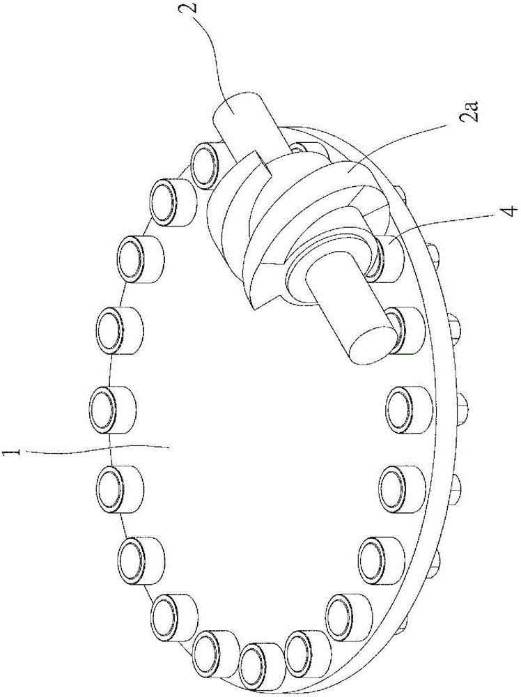
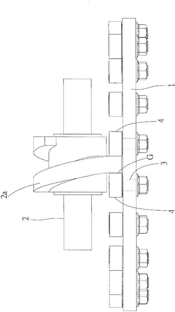
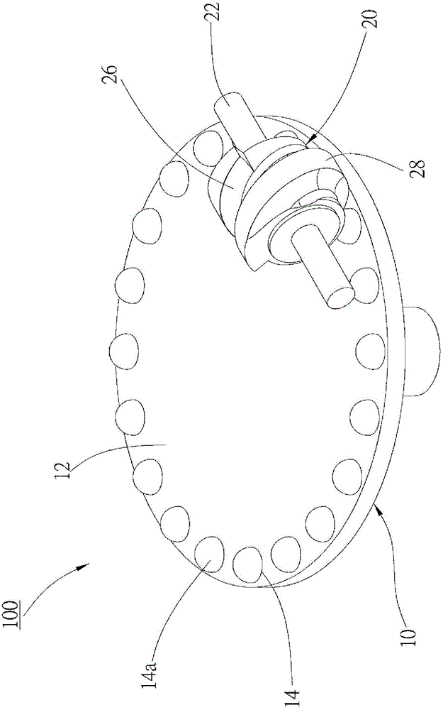
[0016] see Figure 3 to Figure 5 Shown is an intermittent motion transmission mechanism 100 according to a preferred embodiment of the present invention. The transmission mechanism 100 is applied to a processing tool and includes a rotating disk 10 and a camshaft 20 . Wherein the rotating disk 10 is a disk-shaped body, and its disk surface 12 is provided with a plurality of contact pieces 14 at equal intervals along the circumferential direction, and each of the contact pieces 14 has a hemispherical portion 14a exposed outside the disk surface 12 . In this embodiment, it is preferable that each contact piece 14 is accommodated in the corresponding arc-shaped recess 16 of the rotating disk 10 in the form of a spherical body.

[0017] The camshaft 20 of the transmission mechanism 100 is disposed abo...


PUM


Abstract

An intermittent motion transmission mechanism comprises a rotating disc and a camshaft; a plurality of contact parts are arranged on the surface of the rotating disc in the circumferential direction, and each contact part is provided with a hemispherical portion which is exposed out of the disc surface; the camshaft is arranged on one side of the surface of the rotating disc, and comprises a spiral groove; and the bottom of the spiral groove is matched with the hemispherical portions of the contact parts to serve as curved surfaces. The good contact effect between the camshaft and the rotating disc is achieved, and the transmission process is smooth.

Description

technical field [0001] The invention relates to a transmission structure; in particular, it refers to a transmission mechanism for intermittent motion. Background technique [0002] The transmission mechanism for intermittent motion can often be seen in processing tools. Taking the disc tool magazine of the vertical machining center as an example, the transmission mechanism for intermittent motion mainly includes: figure 1 A rotating disk 1 and a camshaft 2 are shown. Wherein, a plurality of cutting tools (not shown) are installed on one side of the rotating disk 1, and a plurality of cylindrical rollers 4 are fixed on the other side of the rotating disk 1 by a plurality of bolts 3; the camshaft 2 has a helical shape and Wide ribs 2a, such as figure 2 As shown, by controlling the camshaft 2 close to the rotating disk 1, and making the rib 2a between two adjacent cylindrical rollers 4, and then driving the camshaft 2, the rib 2a can One side wall pushes the cylindrical ro...

Claims


Application Information

Patent Timeline
IPC IPC(8): F16H27/04F16H53/00
CPCF16H27/04F16H53/00
Inventor 张庆三
Owner SANJET INT
Why Eureka
Try Eureka