Portable Tabacco Fume Combustor

a combustor and tobacco technology, applied in tobacco pipes, applications, tobacco, etc., can solve the problems of restricted non-smoking areas, unrealized, research and development, etc., and achieve the effect of minimizing the problem of secondhand smoking caused by smoking during smoking

Inactive Publication Date: 2013-09-12
JANG CHEOL HO
View PDF5 Cites 7 Cited by
  • Summary
  • Abstract
  • Description
  • Claims
  • Application Information

AI Technical Summary

Benefits of technology

The portable cigarette smoke combustor helps to reduce the harmful substances in secondhand smoke by burning the particles and gas components in the mainstream smoke. This invention minimizes the health risks associated with smoking.

Problems solved by technology

The technical problem addressed in this patent is the harmful substances in cigarette smoke and the need for a method to filter them out.

Method used


Image

  • Portable Tabacco Fume Combustor
  • Portable Tabacco Fume Combustor
  • Portable Tabacco Fume Combustor

Examples


Embodiment Construction

[0020]A portable cigarette smoke combustor according to an exemplary embodiment of the present invention will be described with reference to the accompanying drawings.

[0021]While this invention has been described in connection with what is presently considered to be practical exemplary embodiments, it is to be understood that the invention is not limited to the disclosed embodiments, but, on the contrary, is intended to cover various modifications and equivalent arrangements included within the spirit and scope of the appended claims.

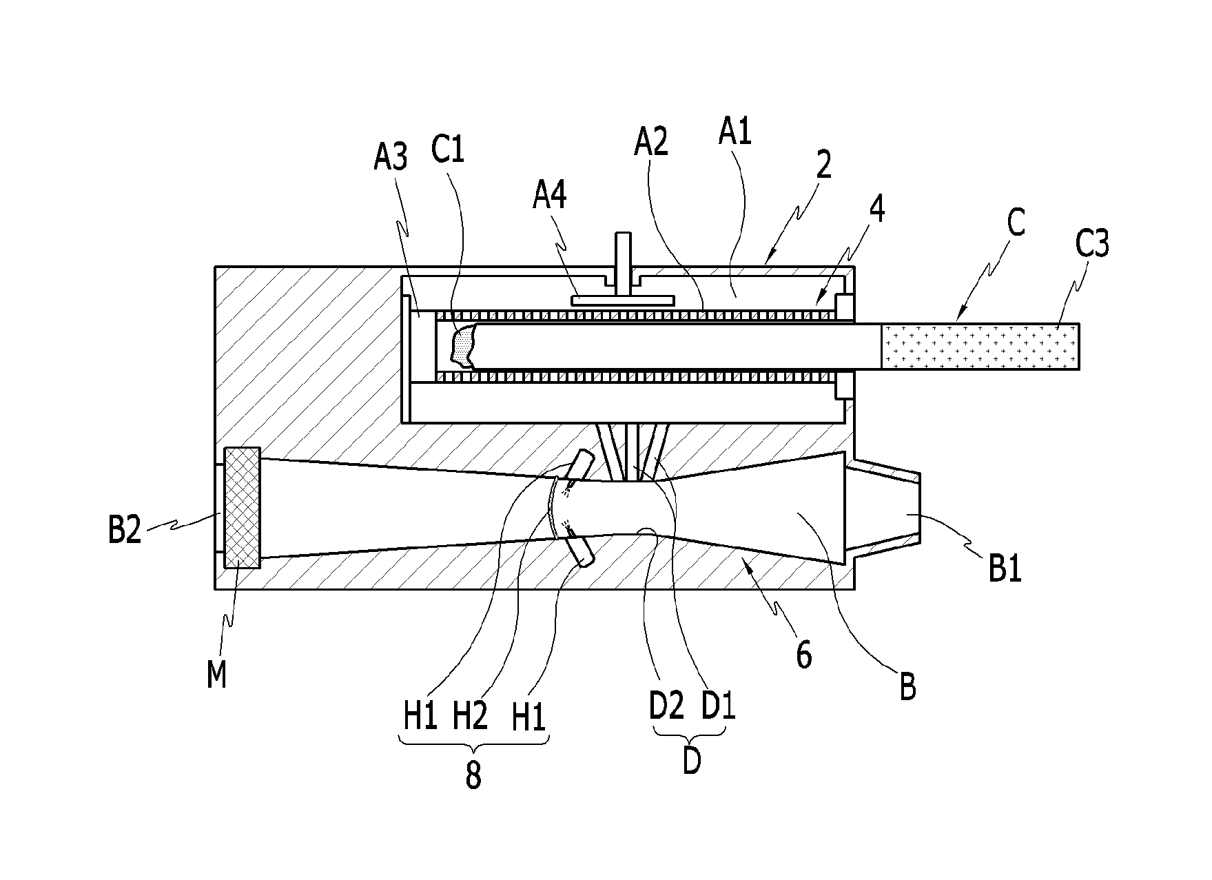
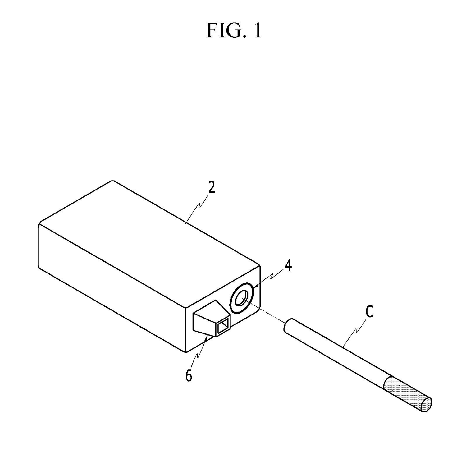
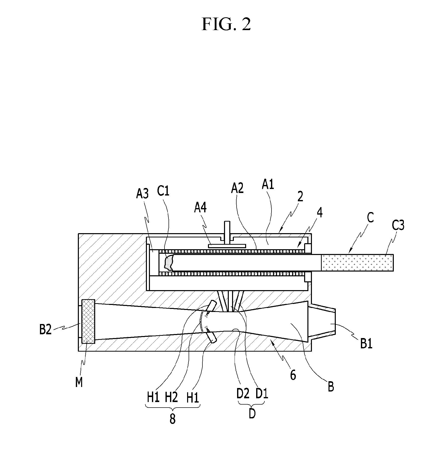
[0022]As shown in FIG. 1 and FIG. 2, a portable cigarette smoke combustor according to the exemplary embodiment of the present invention includes a body 2.

[0023]The body 2 may be made of a heat-resistive and light material, and includes a smoking portion 4 at one side thereof.

[0024]The smoking portion 4 includes a chamber A1 formed in the body 2 and having a size that enables insertion of a cigarette C.

[0025]The chamber A1 is formed along a length direc...


PUM


Abstract

A portable cigarette smoke combustor that can prevent spread of cigarette smoke to the air during smoking is disclosed. The portable cigarette smoke combustor includes: includes: a smoking portion including the first chamber for insertion of a cigarette and a lighter; a cigarette smoke injection portion disposed adjacent to the smoking portion and forming the second chamber for receiving mainstream smoke in the mouth of a smoker; a cigarette smoke combustion portion including a means for combusting cigarette smoke flown into the second chamber; and a sidestream smoke emitting means controlling sidestream smoke generated from the first chamber to flow to the second chamber.
The second chamber is preferably formed as a venture pipe, and the first chamber and the second chamber are connected with each other through a neck portion of the venture pipe.
As the means for combusting the cigarette smoke in the second chamber, a flame generator using a gas or liquid fuel may be used. The flame generator may be provided as a small-sized typical torch and then installed in the second chamber.

Description


Claims


Application Information

Patent Timeline
Owner JANG CHEOL HO
Why Eureka
Try Eureka