Supercharge Your Innovation With Domain-Expert AI Agents!

Medium feeding device

a feeding device and medium-sized technology, applied in the field of medium-sized feeding devices, can solve the problems of reduced processing speed and productivity, increased cost, and large device siz

Active Publication Date: 2013-09-12
PFU LTD
View PDF4 Cites 9 Cited by
  • Summary
  • Abstract
  • Description
  • Claims
  • Application Information

AI Technical Summary

Benefits of technology

The present invention is a medium feeding device comprising a feeding roller, a brake roller and a rotational difference generating unit. The brake roller includes a plurality of rollers that causes a conveyance load on the medium that has entered between the feeding roller and the brake roller, and presses the feeding roller with a predetermined pressure. The rotational difference generating unit generates a rotational difference between one roller and another roller so that the conveyance load acting on the medium by one roller and another roller becomes even when the rollers of the brake roller are divided in an axial direction. This ensures even distribution of the conveyance load on the medium and prevents any excessive pressure on the medium, which could cause damage or compromise the quality of the finished product.

Problems solved by technology

In medium feeding devices having a configuration in which one medium after another is sequentially separated and fed from among a plurality of stacked media, a state called skew, in which a medium is sent in a skewed posture, occurs in some cases due to the effect of, such as, unevenness of pressure load between rollers that send out a medium, or partial contact.
However, for example, the technology described in Japanese Patent Application Laid-open No. 2005-187113 requires dedicated control step for skew correction, such as a step of stopping a medium when pressing a medium against the guide, which may result in reduction of the processing speed and the productivity.
Moreover, the technology described in Japanese Patent Application Laid-open No. 11-189355 has problems that the cost increases and the device becomes large in size and complicated due to provision of special members, such as a unit that detects the amount of skew and the skewed rollers for pressing a medium against the reference guide.

Method used


Image

  • Medium feeding device
  • Medium feeding device
  • Medium feeding device

Examples


first embodiment

[0031]A first embodiment of the present invention is described with reference to FIGS. 1 to 6.

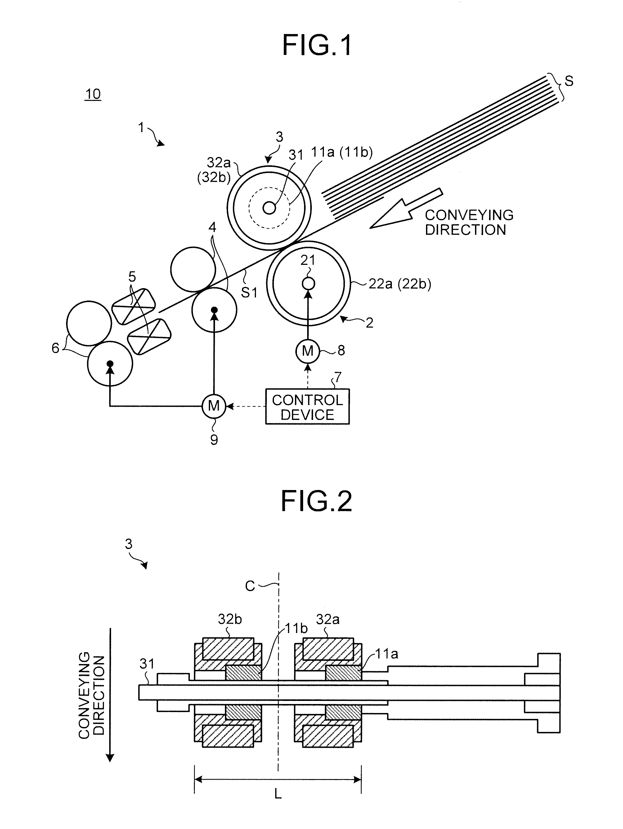
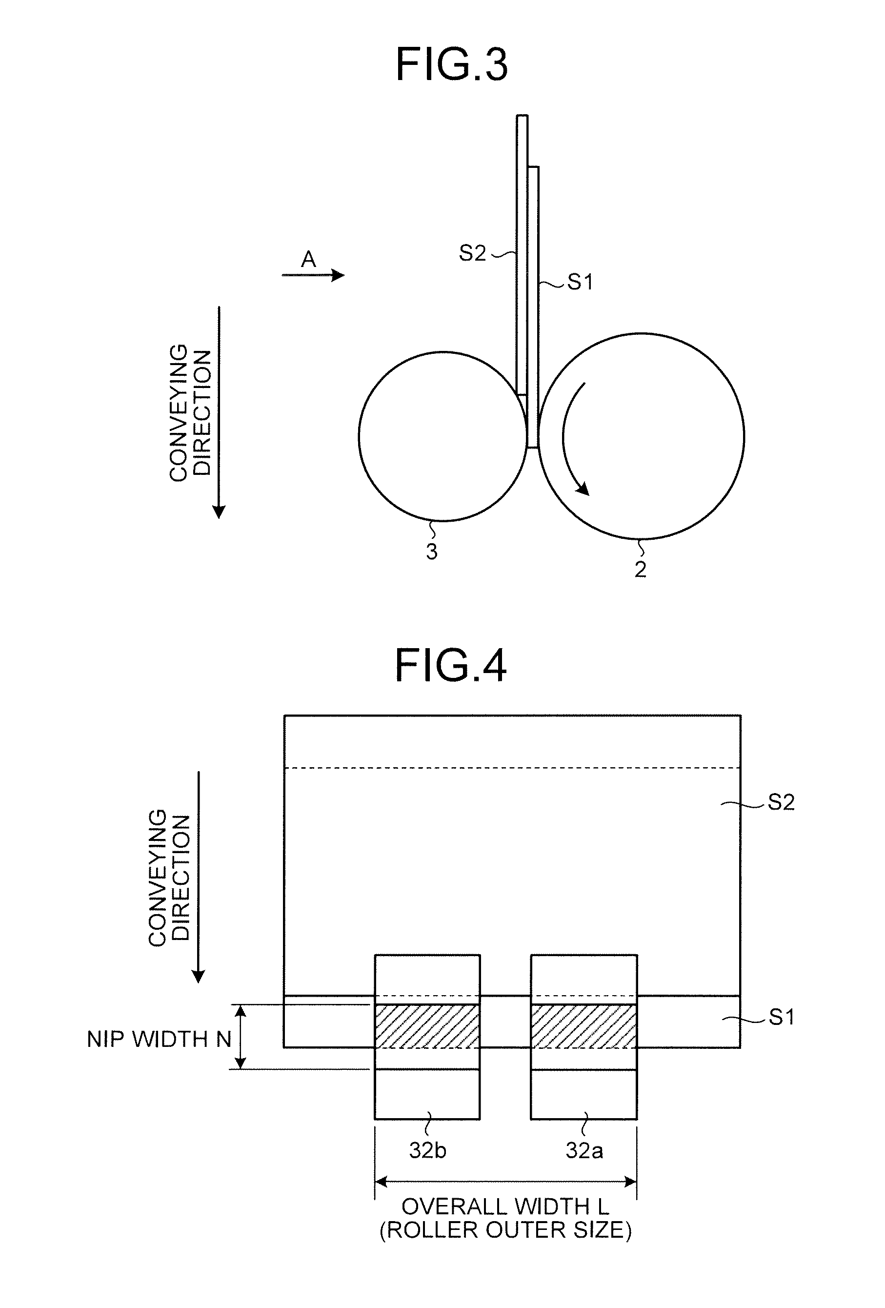
[0032]Referring to FIGS. 1 and 2, the configuration of the medium feeding device according to the first embodiment of the present invention is described first. FIG. 1 is a cross-sectional view that illustrates a schematic configuration of an image reading apparatus on which the medium feeding device according to the first embodiment of the present invention is mounted and FIG. 2 is a plan view that illustrates a schematic configuration of a brake roller of the medium feeding device according to the first embodiment of the present invention.

[0033]As illustrated in FIG. 1, a medium feeding device 1 according to the present embodiment is a device which separates one medium after another from a plurality of stacked sheet-like media S and feeds it. The medium feeding device 1 is applied to an automatic paper feeder (Auto Document Feeder: ADF) mounted on image reading apparatuses, such as an imag...

second embodiment

[0060]Next, a second embodiment of the present invention is described with reference to FIGS. 7 and 8. FIG. 7 is a cross-sectional view that illustrates a schematic configuration of an image reading apparatus on which a medium feeding device according to the second embodiment of the present invention is mounted and FIG. 8 is a plan view that illustrates a schematic configuration of a brake roller of the medium feeding device according to the second embodiment of the present invention.

[0061]As illustrated in FIGS. 7 and 8, a medium feeding device 1a according to the present embodiment is different from the medium feeding device 1 in the first embodiment in that it includes a differential gear 12 between the rollers 32a and 32b of the brake roller 3.

[0062]The differential gear 12 is composed of, for example, two pairs of bevel gears. When there is a difference between the torques that the rollers 32a and 32b receive, the differential gear 12 equalizes the loads by providing a differen...

third embodiment

Modification of Third Embodiment

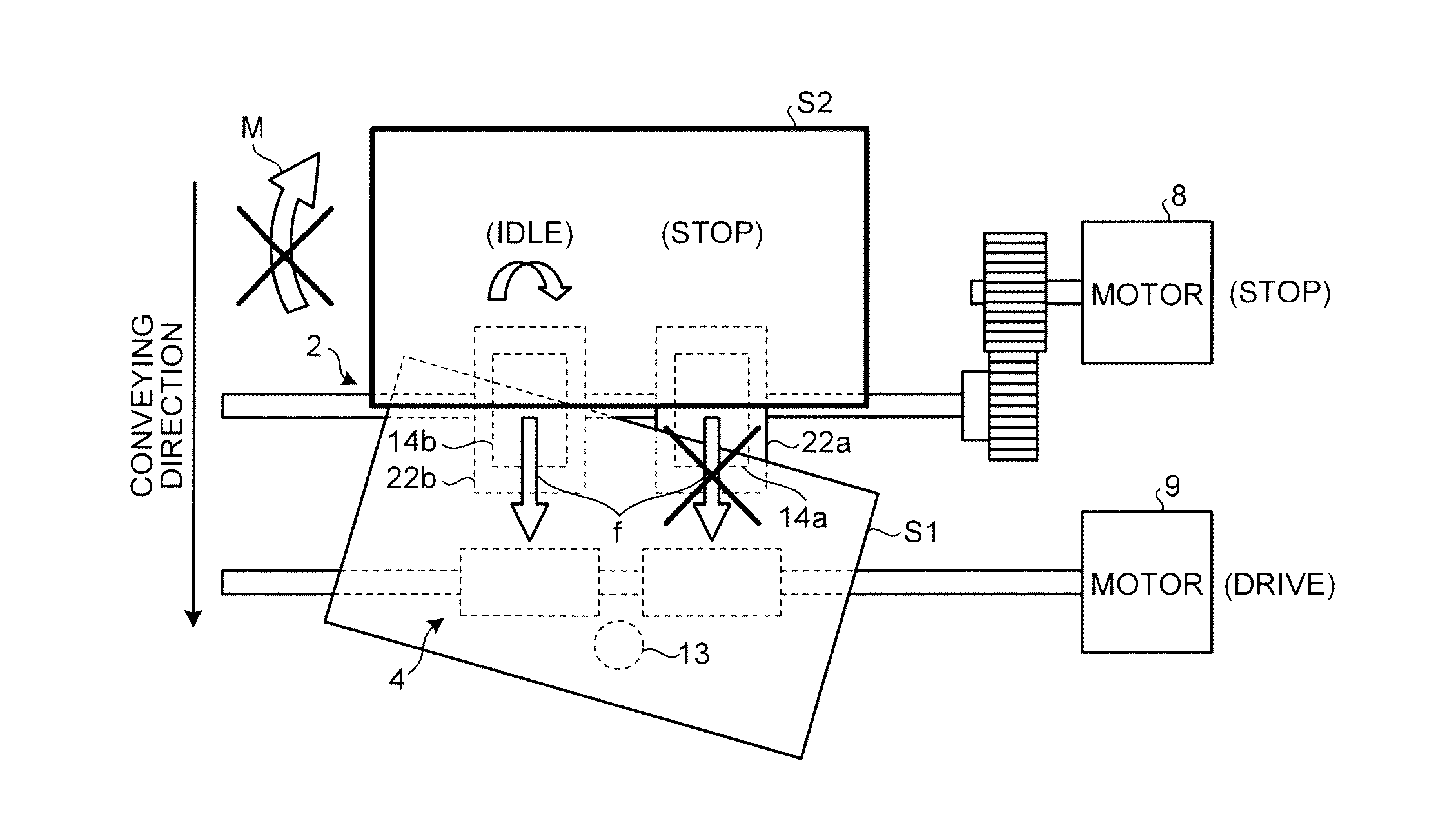
[0098]The medium feeding device 1b in the present embodiment may control driving of the motor 8 such that the circumferential speed of the feeding roller 2 becomes relatively lower than the circumferential speed of the conveying roller 4 instead of the operation of stopping the motor 8 for the feeding roller 2 as the operation when the medium sensors 13 detect the entry of the medium S into the conveying roller 4. In this case, in the operation of the medium feeding device 1b illustrated in FIGS. 11 to 13, switching of the motor 8 from “drive” to “stop” in accordance with the detection by the medium sensors 13 is changed to switching from “drive” to “deceleration”.


PUM


Abstract

A medium feeding device 1 includes a feeding roller 2 that conveys a medium in a conveying direction, and a brake roller 3 that includes rollers 32a and 32b that are arranged to be rotatable around one shaft 31 and cause a conveyance load to act on the medium that has entered between the feeding roller 2 and the rollers 32a and 32b. The rollers 32a and 32b are arranged to press the feeding roller 2 with a predetermined pressure.The medium feeding device 1 further includes a rotational difference generating unit 11 that generates a rotational difference between the rollers 32a and 32b so that the conveyance load acting on the medium by the rollers 32a and 32b becomes even.

Description

CROSS-REFERENCE TO RELATED APPLICATIONS[0001]This application is based upon and claims the benefit of priority from Japanese Patent Application No. 2012-053662, filed on Mar. 9, 2012, the entire contents of which are incorporated herein by reference.BACKGROUND OF THE INVENTION[0002]1. Field of the Invention[0003]The present invention relates to a medium feeding device.[0004]2. Description of the Related Art[0005]In medium feeding devices having a configuration in which one medium after another is sequentially separated and fed from among a plurality of stacked media, a state called skew, in which a medium is sent in a skewed posture, occurs in some cases due to the effect of, such as, unevenness of pressure load between rollers that send out a medium, or partial contact.[0006]As a technology for correcting skew, for example, Japanese Patent Application Laid-open No. 2005-187113 describes a technology in which when occurrence of skew is detected on the basis of a plurality of pieces ...

Claims


Application Information

Patent Timeline
IPC IPC(8): B65H9/00
CPCB65H2403/483B65H9/002
Inventor MOTO, SATORU
Owner PFU LTD
Features
  • R&D
  • Intellectual Property
  • Life Sciences
  • Materials
  • Tech Scout
  • Unparalleled Data Quality
  • Higher Quality Content
  • 60% Fewer Hallucinations
Learn More