Chair or couch with motor-driven movable parts

a motor-driven, chair technology, applied in the field of adjustable seating furniture, can solve the problems of affecting the overall installation, and requiring a long time to complete, so as to facilitate the overall installation

Inactive Publication Date: 2013-09-12
STANZWERK WETTER SICHELSCHMIDT
View PDF7 Cites 7 Cited by
  • Summary
  • Abstract
  • Description
  • Claims
  • Application Information

AI Technical Summary

Benefits of technology

[0017]Also considered as a distinctive characteristic is the fact that a connection socket is provided on the drive motor or on a housing surrounding this motor, the connection socket being accessible from the outside of the housing for the plugging in or contacting, which connection socket is permanently attached to the motor connector cable, and to which connection socket the connector cable can be mechanically or electrically connected by a matching connector component. A corresponding configuration can be provided for both the drive unit as well as the seat. Here the cable outlet from the motor or from the motor housing is essentially created by a socket that is connected at one end by connecting wires to the drive motor. The connection externally is effected in the form of a plug-in connection that is accessible from the outside. With this arrangement the cable connected to the motor does not exits the housing or the like and is routed to the retaining bracket. Instead the connector cable that is preferably routed outside can, on the one hand, be plugged by the one end section into the connection socket so as to make contact and be mechanically connectable, while the other end of the connector cable has the connector plug. The overall installation is facilitated even further thereby since the motor can be installed in finished form, optionally with a housing surrounding the motor including electrical wiring, while connecting to the connector socket leading to the motor with the connector cable can be effected subsequently, that is, during a later operation.

Problems solved by technology

Running the incoming cable within the chair is relatively costly and complex, and in particular takes quite some time.
This is costly in terms of the assembly and is associated with relatively high manufacturing costs.

Method used


Image

  • Chair or couch with motor-driven movable parts
  • Chair or couch with motor-driven movable parts
  • Chair or couch with motor-driven movable parts

Examples


Embodiment Construction

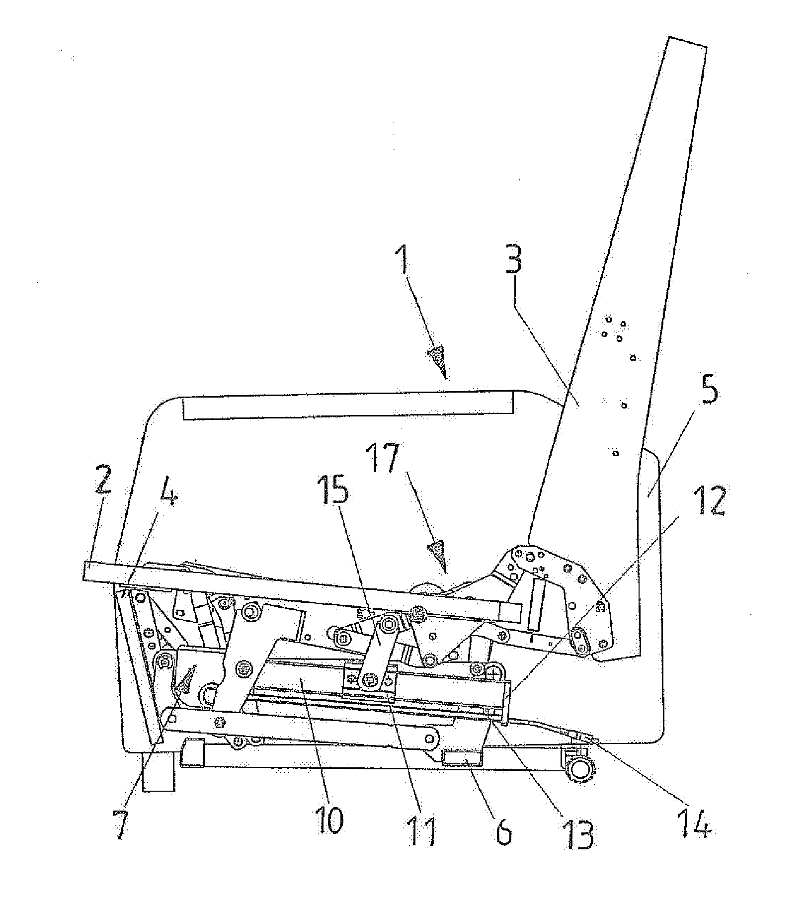
[0022]As seen in FIG. 1 a couch or chair 1 has a generally horizontal seat 2, an upright back 3 projecting up from a rear end of the seat 2, and a footrest 4 projecting down from a front end of the seat 2, all shown without upholstery or cushions for clarity of view. These parts 2, 3, and 4 are all slidable and / or pivotal on a frame 5 having a longitudinal floor beam 6 by a linkage 17.

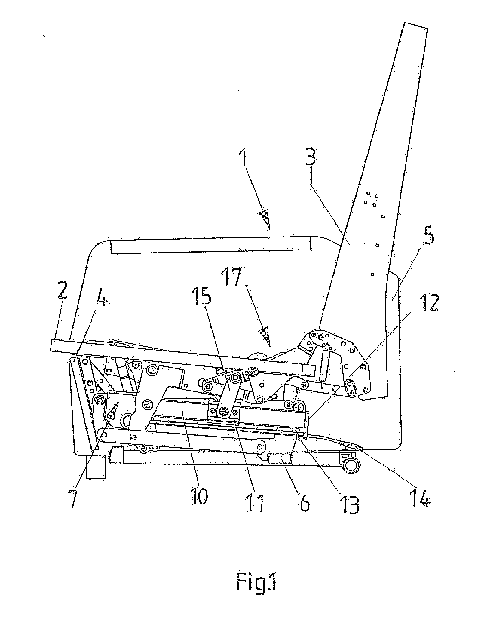
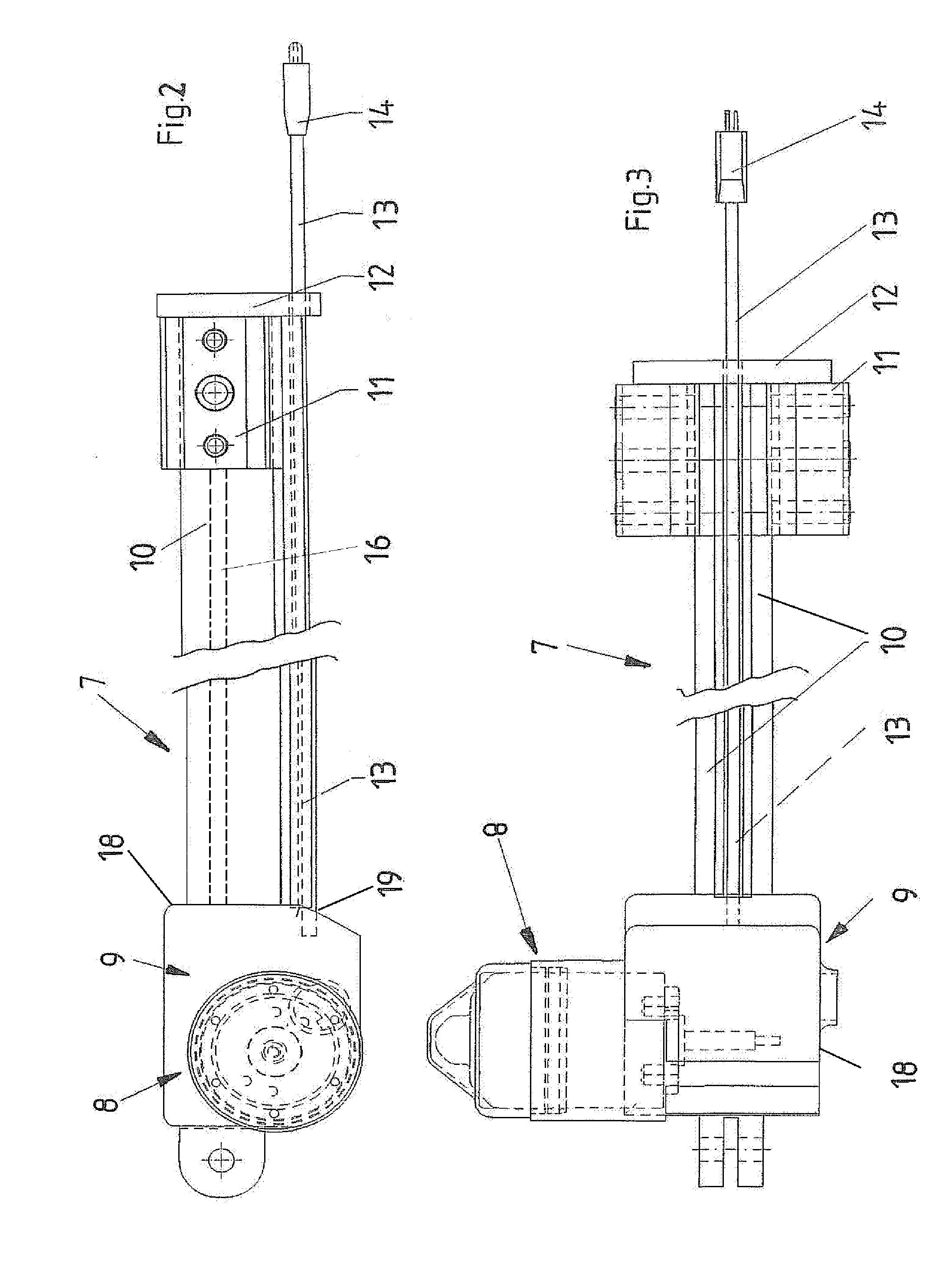
[0023]In addition, an electric-motor-driven drive 7 is attached, for example, to the beam 6 and serves for operating the linkage 17. It has an electric drive motor 8 with a step-down transmission 9. A tube 10 extends from a housing 18 surrounding the motor 8 and transmission 9 and coaxially receives a drive element, such as, for example, a threaded spindle 16 that is operatively connected to the step-down transmission 9.

[0024]An adjustment slide 11 can move along the outer surface of the tube 10, with its longitudinal front-to-back position determined by the drive element 16, so that it connects this d...


PUM


Abstract

A couch or chair has a frame, a movable seat, a movable back, a movable footrest, and a linkage connected to the seat, back, and footrest to shift same between different positions on the frame. A drive has a motor, a transmission, a drive housing holding the motor and transmission and secured to the frame underneath the seat, and a rigid tube having a front end fixed to the housing and a rear end. A mounting bracket fixed to the rear end of the tube is secured to the frame, and a drive element in the tube is connected to the transmission. A slide on the tube between the ends thereof engages the drive element and is connected to the linkage to shift the seat, back, and footrest. A cable is connected to the motor, extends rearward along the tube past the bracket, and carries a plug.

Description

FIELD OF THE INVENTION[0001]The present invention relates to a piece of adjustable seating furniture. More particularly this invention concerns a chair or couch with motor-driven movable parts.BACKGROUND OF THE INVENTION[0002]The invention relates to a piece of seating furniture, that is a couch or chair, with parts that are adjustable by an electric motor, and that specifically include at least one seat and / or back and / or footrest. The piece of furniture has a frame normally comprised of two vertical end members or plates interconnected by front and back longitudinal beams on which parts of the adjustment mechanism of the adjustable parts are pivotally linked or attached.[0003]A drive having an electric motor is attached to parts of the adjustment mechanism and also has a step-down transmission as well as a tube that projects from the motor and transmission and that surrounds a drive element, in particular, a threaded drive spindle that is operatively connected to the step-down tra...

Claims


Application Information

Patent Timeline
Patent Type & Authority Applications(United States)
IPC IPC(8): A47C1/035
CPCA47C1/034A47C1/03211A47C1/0242
Inventor SICHELSCHMIDT, CHRISTOPH
Owner STANZWERK WETTER SICHELSCHMIDT
Why Eureka
Try Eureka