Contact device

a contact device and arc expansion technology, applied in the direction of contact mechanisms, electromagnetic relay details, electrical apparatus, etc., can solve the problem of limited arc expansion width direction of the arcscope, and achieve the effect of reducing friction force, reducing arc interruption capacity, and expanding the bas

Inactive Publication Date: 2013-09-12
PANASONIC INTELLECTUAL PROPERTY MANAGEMENT CO LTD
View PDF3 Cites 25 Cited by
  • Summary
  • Abstract
  • Description
  • Claims
  • Application Information

AI Technical Summary

Benefits of technology

[0012]According to the present invention, the rotation stoppers that regulate the rotation of the movable contact member are provided between the movable contact member and the base, and are formed separately from the movable contact member. Therefore, the base can be enlarged compared with conventional cases since it is not necessary to bring the movable contact member into contact with the inner wall surface of the base to regulate the rotation of the movable contact member. Further, since the rotation of the movable contact member can be regulated even if the base is enlarged, the space for the arc can be expanded sufficiently not only in the longitudinal direction but also in the width direction of the movable contact member. As a result, the arc generated at the point of contact and separ

Problems solved by technology

When an arc, which is generated at the point of contact and separation between the movable contact points and the fixed contact points, is extended, th

Method used


Image

  • Contact device
  • Contact device
  • Contact device

Examples


Embodiment Construction

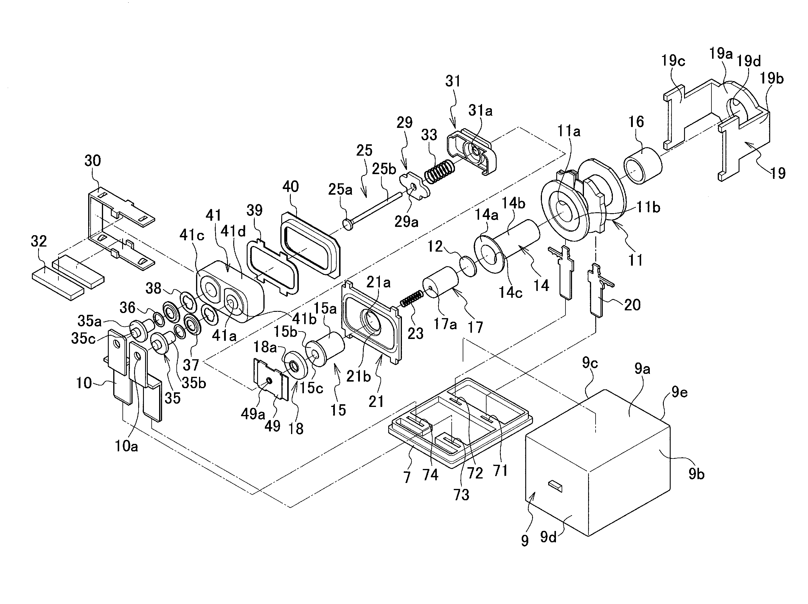
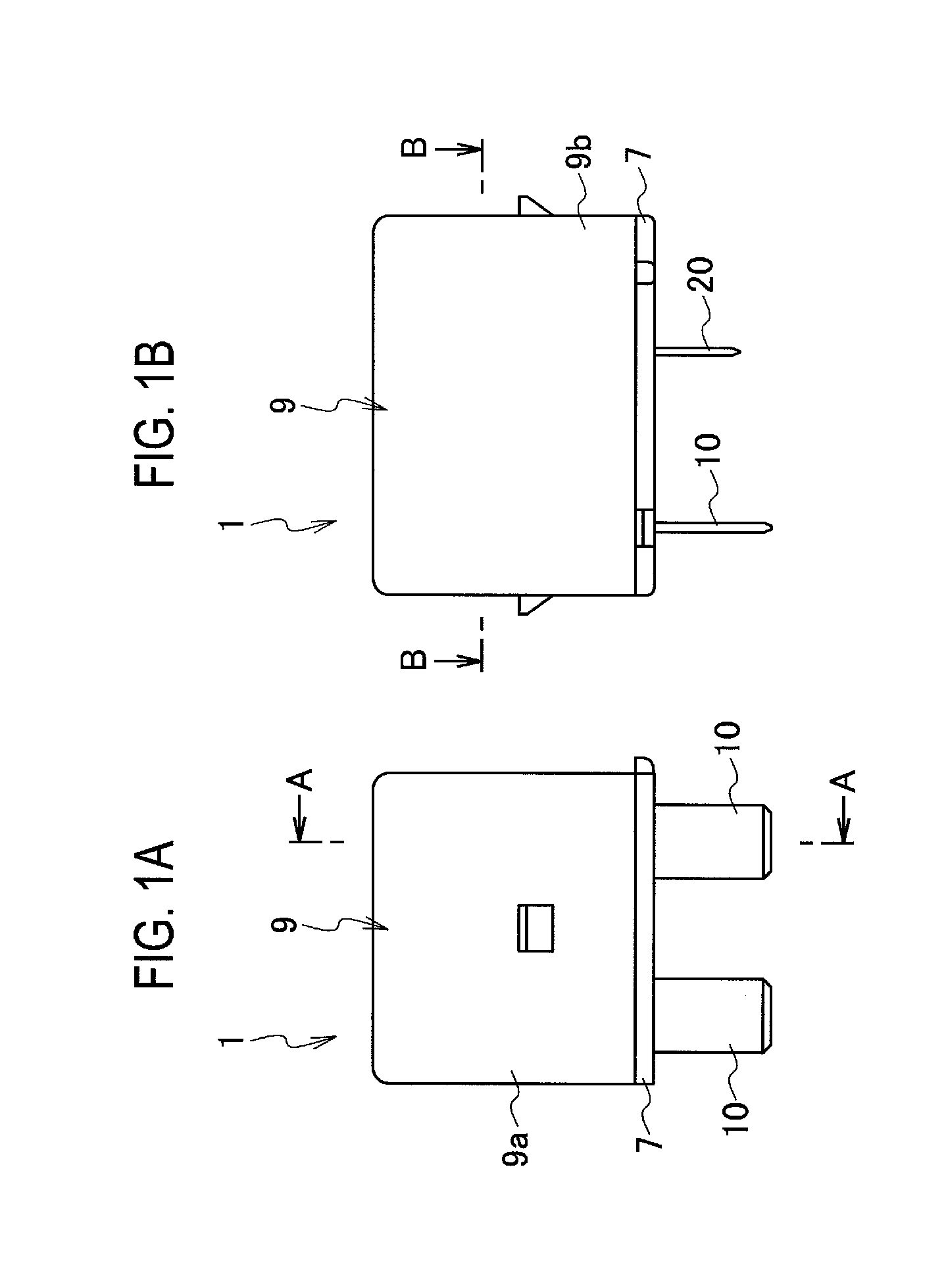
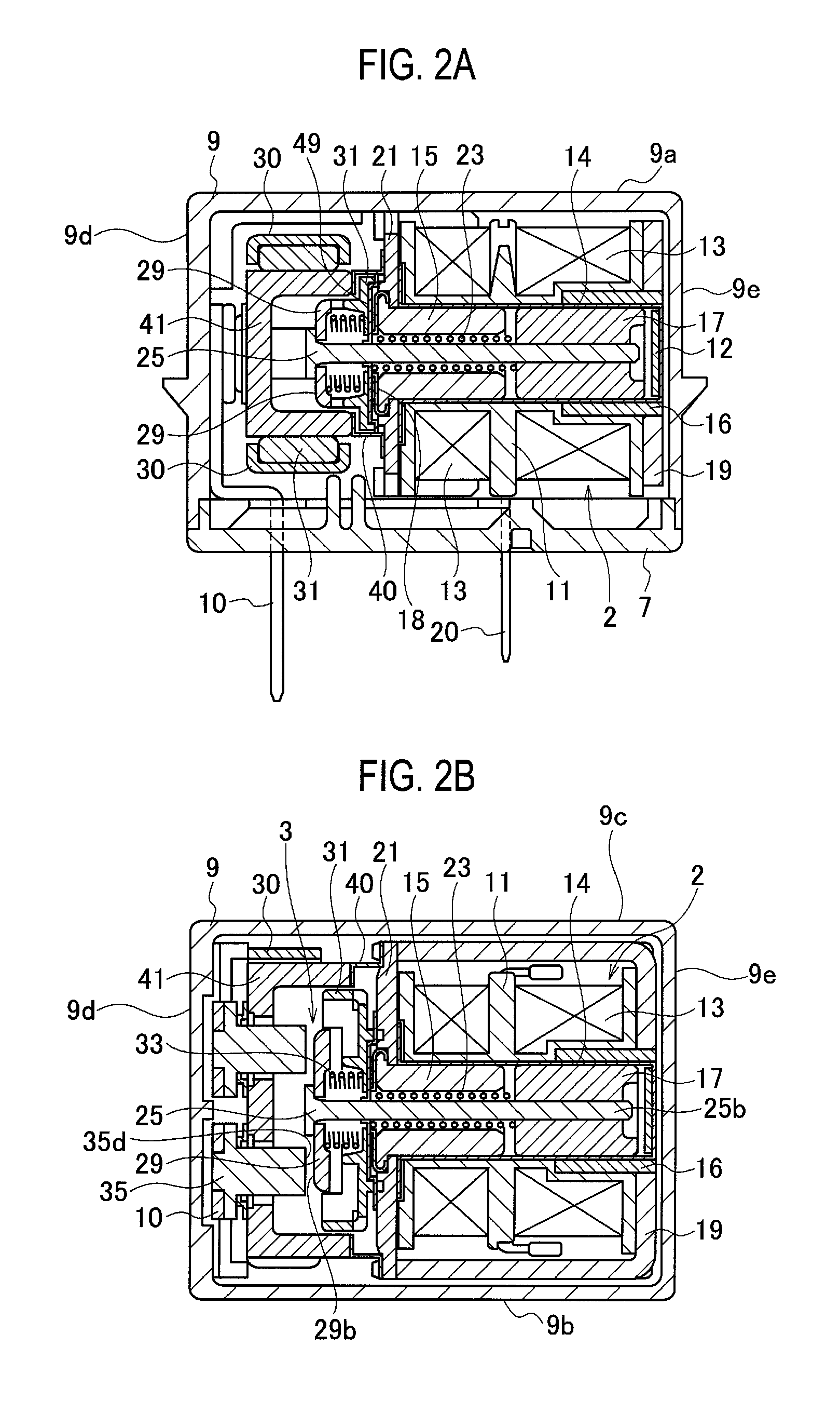
[0025]An embodiment of the present invention is explained in detail below with reference to the drawings. First, a schematic configuration of a contact device 1 according to the embodiment of the present invention is explained with reference to FIG. 1 to FIG. 3.

[0026]The contact device 1 according to the present embodiment is applied to an electromagnetic relay. The contact device 1 includes a drive member 2 located on the rear side (on the right) in FIG. 2A and FIG. 2B, and a contact member 3 located on the front side (on the left) in FIG. 2A and FIG. 2B. The drive member 2 and the contact member 3 are housed in a case.

[0027]The case includes a case base portion 7 formed into substantially a rectangular shape, and a case cover 9 provided over the case base portion 7 that houses installed members such as the drive member 2 and the contact member 3. As shown in FIG. 3, the case base portion 7 is provided (on the rear side) with a pair of slits 71 and 72 in which coil terminals 20 are...


PUM


Abstract

A contact device (1) includes a base (41), a movable contact member (29) stored inside the base (41), and one or more rotation stoppers (50) formed separately from the movable contact member (29) and provided between the movable contact member (29) and the base (41) so as to regulate a rotation of the movable contact member (29). At least one rotation stopper (50) regulates a movement in one rotating direction of the movable contact member (29).

Description

CROSS REFERENCE TO RELATED APPLICATION[0001]This application is based upon and claims the benefit of priority from Japanese Patent Application No. 2012-053066, filed on Mar. 9, 2012, the entire contents of which are incorporated herein by reference.BACKGROUND OF THE INVENTION[0002]The present invention relates to a contact device.[0003]As described in Japanese Patent Unexamined Publication No. 2010-192416, there is known a contact device including a movable contact member provided with movable contact points, a base that houses the movable contact member, and rotation stoppers provided between the movable contact member and the base. The rotation stoppers regulate the rotation of the movable contact member at the point of coming into contact with and separating from fixed contact points.[0004]In Japanese Patent Unexamined Publication No. 2010-192416, the movable contact member is provided with protrusions as the rotation stoppers on each long side. When the movable contact member ro...

Claims


Application Information

Patent Timeline
IPC IPC(8): H01H50/64
CPCH01H50/643H01H50/546H01H1/34H01H1/64H01H50/54
Inventor NISHIMURA, TSUKASA
Owner PANASONIC INTELLECTUAL PROPERTY MANAGEMENT CO LTD
Why Eureka
Try Eureka