Illumination device

a technology of illumination device and illumination intensity, which is applied in the direction of lighting and heating apparatus, point-like light sources, and long light sources, can solve the problems of glare and luminance difference, and achieve the effects of alleviating or eliminating luminance differences, uniform illumination intensity, and alleviating luminance differences

Active Publication Date: 2013-09-12
MINEBEAMITSUMI INC
View PDF2 Cites 24 Cited by
  • Summary
  • Abstract
  • Description
  • Claims
  • Application Information

AI Technical Summary

Benefits of technology

[0010]In view of the problems described above, the present invention provides an illumination device capable of obtaining a uniform illumination intensity across a wide area and alleviating a luminance difference generated by a hot spot by guiding light emitted from a plurality of light-emitting diodes without using a light guide plate.
[0028]According to the present invention, in an illumination device where the light emitted from a plurality of light-emitting diodes is guided and emitted without using a light guide plate, it is possible to obtain a uniform illumination intensity across a wide range and alleviate or eliminate a luminance difference caused by generation of a hot spot.

Problems solved by technology

In a case where the illumination device 100 is configured as an LED illumination device in this manner, there may be a problem in that hot spots may be generated in the vicinity of an area straightly under each light source 105, and a luminance difference between the hot spots and other portions may occur flaring (glare) giving viewers unpleasant senses.

Method used


Image

  • Illumination device
  • Illumination device
  • Illumination device

Examples


first embodiment

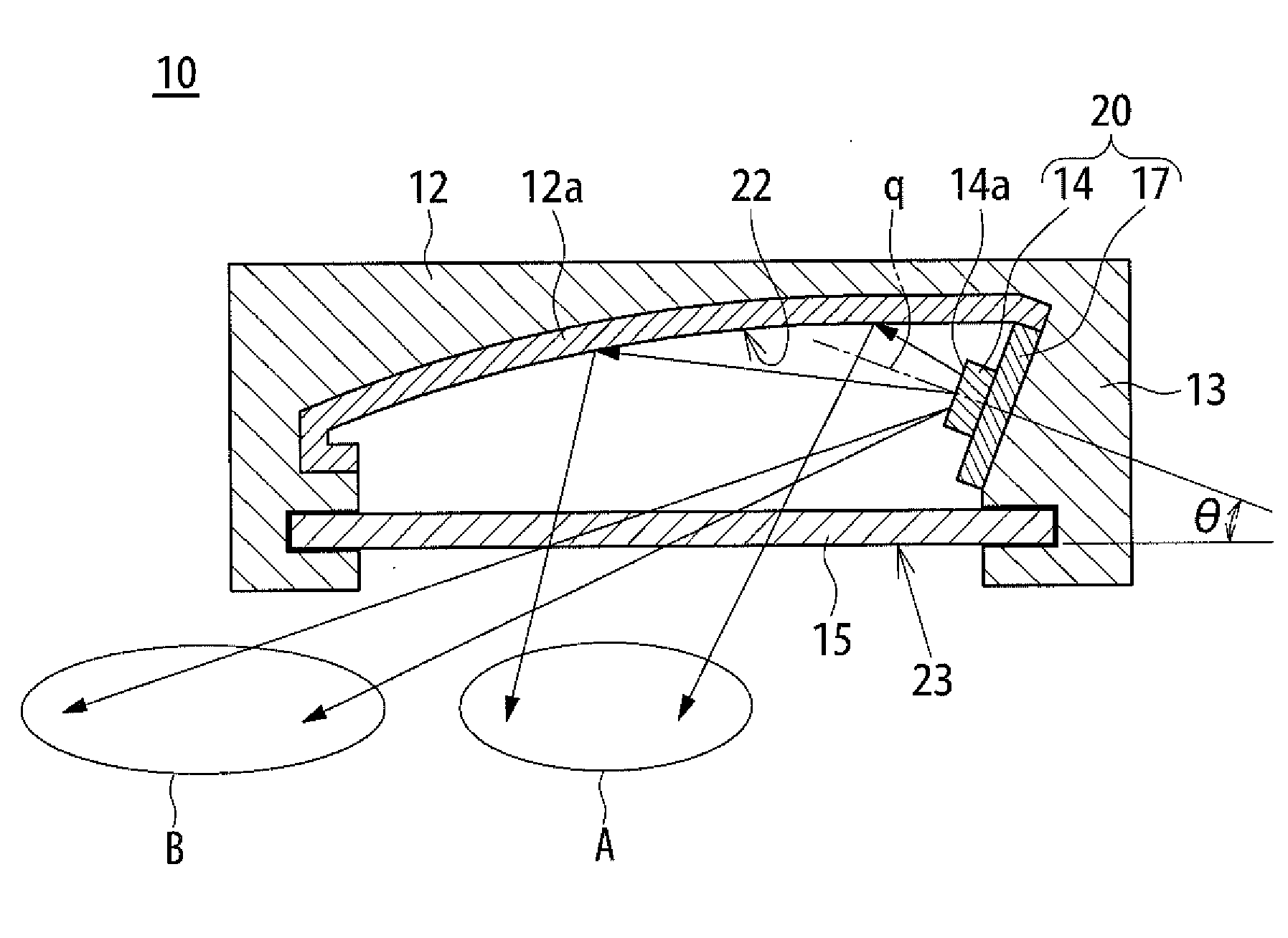
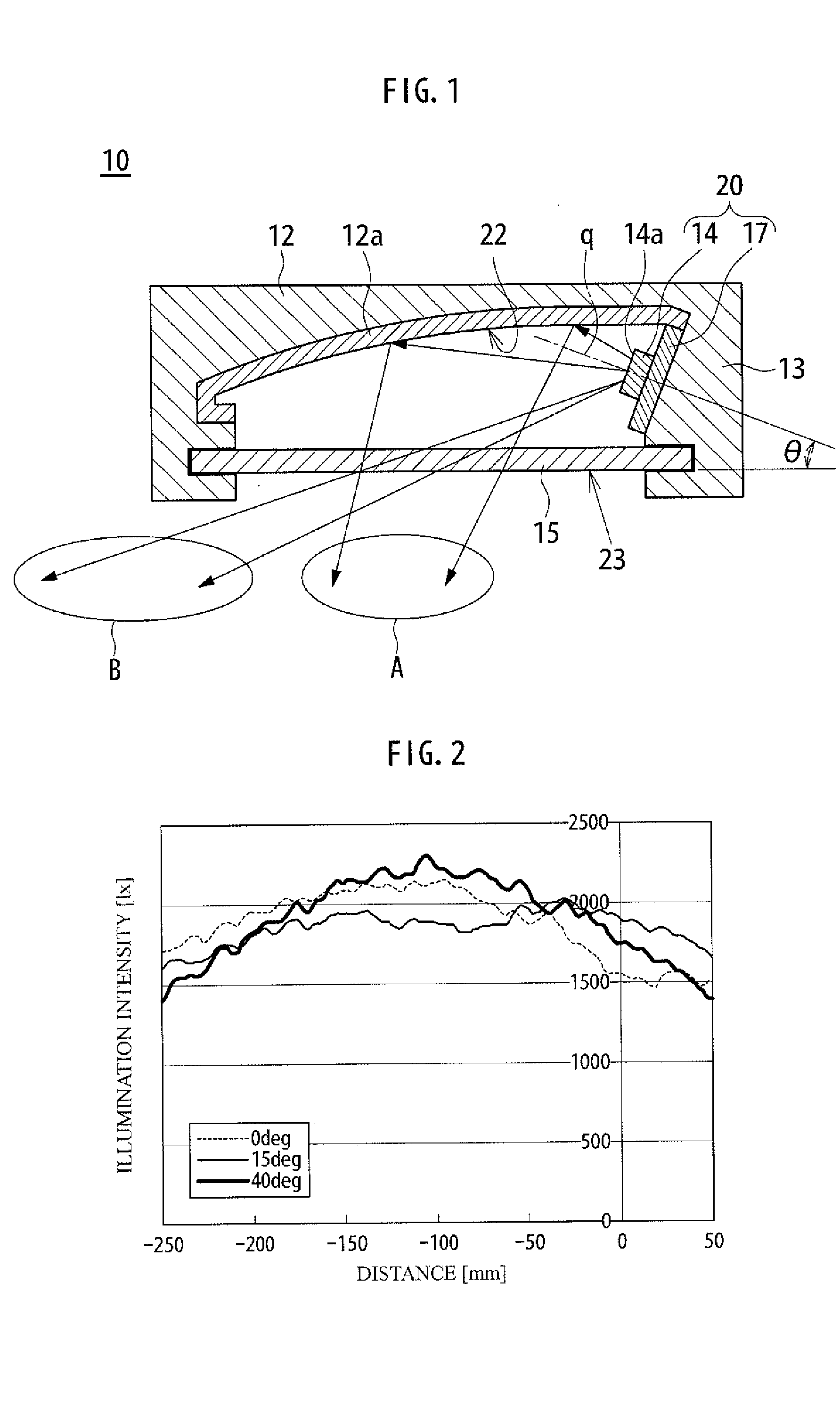
[0038]An illumination device 10 according to the present invention includes a light source unit 20 having a plurality of light-emitting diodes (hereinafter, also referred to as LEDs) 14 arranged in a linear shape. FIG. 1 is a cross-sectional view of the illumination device 10 illustrating one of the LEDs 14 taken along a line perpendicular to an arrangement direction of the LEDs 14.

[0039]The illumination device 10 further includes a diffusion panel 15 arranged to extend to one side (left side in FIG. 1) from the vicinity of an area straightly under the light source unit 20, a first reflective body 12 arranged to extend to the same side to which a light-emergent face 23 extends from the vicinity of an area straightly over the light source unit 20, and a side wall 13 where the light source unit 20 is fixed. The light-emergent face 23 of the illumination device 10 includes a lower face (principal face directed to the outer side of the device) of the diffusion panel 15. As a result, the...

second embodiment

[0062]Next, an illumination device 40 according to the present invention will be described with reference to FIG. 4. It is noted that the illumination device 40 is similar to the illumination device 10 of FIG. 1 except for a second reflective face 55. Therefore, the following description will be generally given for a difference between the illumination devices 10 and 40 without repeating the description of similar parts.

[0063]Referring to FIG. 4, in the illumination device 40, a light-emergent face 63 is defined as a virtual design surface extending to one side (left side in FIG. 4) from the vicinity of an area straightly under the light source unit 20 (the circuit board 17 is not illustrated intentionally) by way of example. However, the illumination device 40 may include the diffusion panel 15 similar to that of the illumination device 10.

[0064]The illumination device 40 according to the present embodiment further includes a second reflective body 54 extending to the same side to ...


PUM


Abstract

The illumination device includes a light source unit having a plurality of LEDs arranged in a linear shape, a light-emergent face extending to one side from the vicinity of an area straightly under the light source unit, and a first reflective body extending to the same side to which the light-emergent face extends from the vicinity of an area straightly over the light source unit, wherein the first reflection body has a first reflection face configured to get close to the light-emergent face as the first reflective body extends from the vicinity of an area straightly over the light source unit, and the light source unit is provided such that an optical axis of the LED is inclined to the first reflective face side with respect to a direction parallel to the light-emergent face.

Description

BACKGROUND OF THE INVENTION[0001]1. Field of the Invention[0002]The present invention relates to an illumination device, and more particularly, to an illumination device that guides light emitted from a light source arranged in a lateral side with respect to a light-emergent face without using a solid light guide plate, and that emits the light from the light-emergent face.[0003]2. Description of the Related Art[0004]Conventionally, there has been proposed a light-guide-less type illumination device, in which a light source is disposed in a lateral side with respect to a light-emergent face to guide and emit the light from the light source toward the light-emergent face, and the light passes through the air without using a solid light guide plate (refer to JP 2007-294252 A, for example).[0005]FIG. 7 illustrates an illumination device disclosed in JP 2007-294252 A. An illumination device 100 illustrated in FIG. 7 includes a reflective body 110 obtained by laminating a reflective shee...

Claims


Application Information

Patent Timeline
Patent Type & Authority Applications(United States)
IPC IPC(8): F21V7/00F21V13/04
CPCF21V7/0066F21V13/04F21V7/0008F21V7/0041F21Y2103/003F21V7/06F21V13/02F21Y2101/02F21V7/005F21Y2103/10F21Y2115/10
Inventor OHNO, YASUOKATO, SHUN
Owner MINEBEAMITSUMI INC
Why Eureka
Try Eureka