Balance correction weight providing constant mass

a technology of constant mass and balance, applied in the direction of soldering apparatus, machine/engine, forging/pressing/hammering apparatus, etc., can solve the problems of higher maintenance costs and turbine damag

Active Publication Date: 2013-09-12
SIEMENS ENERGY GLOBAL GMBH & CO KG
View PDF3 Cites 5 Cited by
  • Summary
  • Abstract
  • Description
  • Claims
  • Application Information

AI Technical Summary

Benefits of technology

[0013]It may be an object of the present invention to prov

Problems solved by technology

An unbalance of the movable turbine parts leads to damages of the t

Method used


Image

  • Balance correction weight providing constant mass
  • Balance correction weight providing constant mass
  • Balance correction weight providing constant mass

Examples


Embodiment Construction

[0040]The illustrations in the drawings are schematical. It is noted that in different figures, similar or identical elements are provided with the same reference signs.

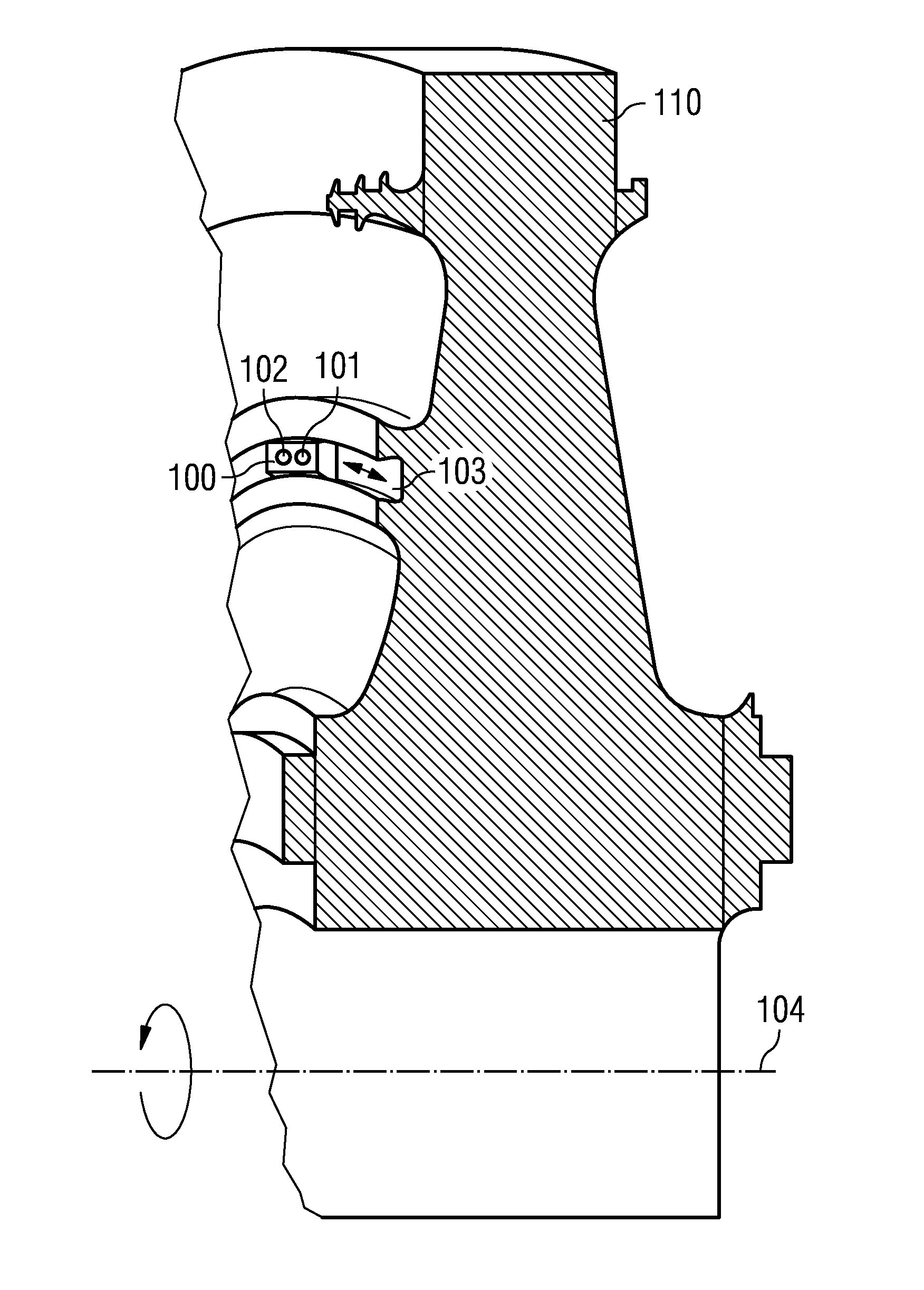
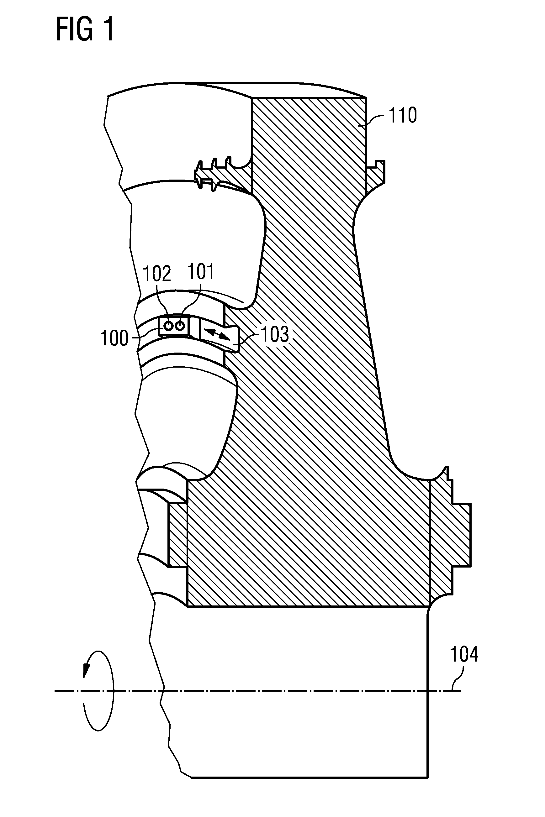
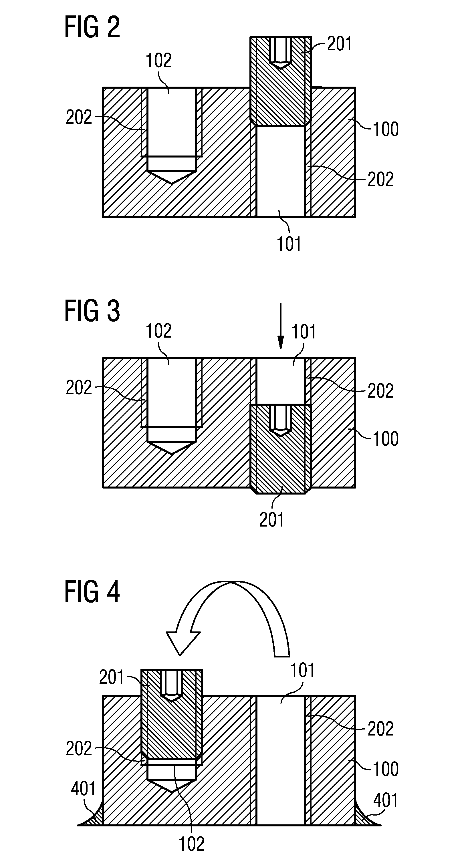
[0041]FIG. 1 shows the system for balancing a movable turbine part 110 of a turbine. The system comprises a balancing weight element 100 with a first hole 101 and a second hole 102. Moreover, the balancing weight element 100 comprises a fixing element 201 (see FIG. 2). The first hole 101 and the second hole 102 are formed in such a manner that the fixing element 201 is detachably insertable in either the first hole 101 or the second hole 102. The first hole 101 is formed in such a manner that the inserted fixing element 105 in the first hole 101 detachably couples the balancing weight element 100 to the movable turbine part 110 in a spatially fixed position.

[0042]The second hole 102 is formed in such a manner that the fixing element 201 is receivable in the second hole 102, when the balancing weight element 100 is no...


PUM

PropertyMeasurementUnit
Weightaaaaaaaaaa

Abstract

A system is provided for balancing a movable turbine part of a turbine or of a compressor. The system includes a balancing weight element with a first hole and a second hole and a fixing element. The first hole and the second hole are formed in such a manner that the fixing element is detachably insertable in either the first hole or the second hole. The first hole is formed in such a manner that the inserted fixing element in the first hole detachably couples the balancing weight element to the movable turbine part in a spatially fixed position. The second hole is formed in such a manner that the fixing element is receivable in the second hole.

Description

FIELD OF INVENTION[0001]The present invention relates to a system for balancing a movable turbine part of a turbine or of a compressor, to a movable turbine part of a turbine or of a compressor as well as to a method of balancing a movable turbine part of a turbine or of a compressor.ART BACKGROUND[0002]In turbines or compressors, in particular in gas turbines, movable turbine parts, such as rotor blades in a compressor stage or in a turbine stage, rotate with a high rotary speed around a turbine shaft. In order to prevent an unbalance during rotation, balancing weights have to be placed to the movable turbine parts for balancing the movable parts. An unbalance of the movable turbine parts leads to damages of the turbine, e.g. in the bearings, and thus to higher maintenance costs.[0003]In order to balance the movable parts of the turbine, the balance weights are fixed to the movable turbine parts in a balanced position. In the balance position, the balancing weights are permanently ...

Claims


Application Information

Patent Timeline
IPC IPC(8): F01D25/04
CPCF01D5/027F16F15/34F05D2260/30F01D25/04F05B2260/966Y10T29/4932B23K26/345B23K35/0244F01D1/24F01D5/005B23K2201/001B23K26/3213B23K2101/001B23K2103/08B23K26/32B23K26/342
Inventor MILNER, GLYNN
Owner SIEMENS ENERGY GLOBAL GMBH & CO KG
Why Eureka
Try Eureka