Injection stretch blow molding device and molded part heating device

a heating device and injection stretch technology, which is applied in the direction of mechanical conveyors, domestic applications, other domestic articles, etc., can solve the problem that the thermal energy required to heat the preform to the optimum blow temperature is unnecessary

Active Publication Date: 2013-09-12
NISSEI ASB MASCH CO LTD
View PDF5 Cites 18 Cited by
  • Summary
  • Abstract
  • Description
  • Claims
  • Application Information

AI Technical Summary

Benefits of technology

[0133]According to the embodiments of the invention, the difference in molding temperature in each operation when subjecting N preforms simultaneously produced by injection molding to blow molding in n operations in units of M preforms, can be reduced when using the 1.5-stage method. The details thereof are described below with reference to FIG. 10 using a comparative example.
[0134]FIG. 10 shows the preform temperature TE according to one embodiment of the invention, and the preform temperature TC in the 1.5-stage device disclosed in Japanese Patent No. 2954858 (comparative example). In one embodiment of the invention, twenty-four (N=24) preforms were simultaneously produced by injection molding, subjected to forced cooling, heated, and then subjected to blow molding in units of eight (M=8) preforms. In the comparative example, eight preforms were simultaneously produced by injection molding, heated during intermittent transfer, and then subjected to blow molding in units of four preforms.
[0135]In FIG. 10, the time T1 is the forced cooling period using the cooling section 20 according to one embodiment of the invention, the time T2 is the intermittent transfer time using the heating section according to the comparative example, and the time T3 is the continuous transfer time using the heating section 30 according to one embodiment of the invention.
[0136]In the comparative example shown in FIG. 10, the temperature of four preforms that are initially subjected to blow molding increases by heating according to the characteristics TC1, and the temperature of four preforms that are subsequently subjected to blow molding increases by heating according to the characteristics TC2. The characteristics TC1 and the characteristics TC2 differ as to the temperature immediately before heating. A relatively large temperature difference Δt is observed between the characteristics TC 1 and the characteristics TC2. The temperature difference Δt also occurs during blow molding (see FIG. 10).
[0137]In one embodiment of the invention shown in FIG. 10, the temperature of eight preforms that are initially subjected to blow molding increases by heating according to the characteristics TE1, the temperature of eight preforms that are subsequently subjected to blow molding increases by heating according to the characteristics TE2, and the temperature of eight preforms that are subsequently subjected to blow molding increases by heating according to the characteristics TE3. The characteristics TE1, the characteristics TE2, and the characteristics TE3 differ as to the temperature immediately before heating. However, the temperature difference ΔT between the characteristics TE1, the characteristics TE2, and the characteristics TE3 is significantly smaller than the temperature difference Δt in the comparative example. The small temperature difference ΔT also occurs during blow molding (see FIG. 10).
[0138]Specifically, when using the 1.5-stage method in which preforms simultaneously produced by injection molding are separately subjected to blow molding in n operations, the temperature of preforms that are initially subjected to blow molding tends to be higher than the temperature of preforms that are subsequently subjected to blow molding. This is because the time from the completion of injection molding to the start of heating is inevitably shorter for the initial heating operation than for the subsequent heating operation. The above tendency significantly occurs when the heating section heats preforms that are initially subjected to blow molding and preforms that are subsequently subjected to blow molding among the preforms simultaneously produced by injection molding while transferring the preforms in a row. Specifically, the heating start time after completion of injection molding differs in units of preforms that are simultaneously subjected to blow molding.

Problems solved by technology

According to the 1-stage (hot parison) method, since the preform that retains heat applied during injection molding is subjected to blow molding to obtain a container, the thermal energy that is required for heating the preform to room temperature to the optimum blow temperature is unnecessary.

Method used


Image

  • Injection stretch blow molding device and molded part heating device
  • Injection stretch blow molding device and molded part heating device
  • Injection stretch blow molding device and molded part heating device

Examples


Embodiment Construction

[0089]Exemplary embodiments of the invention are described in detail below with reference to a comparative example. Note that the following exemplary embodiments do not in any way limit the scope of the invention defined by the claims laid out herein. Note also that all of the elements described in connection with the following exemplary embodiments should not necessarily be taken as essential elements of the invention.

1. Injection Stretch Blow Molding Device

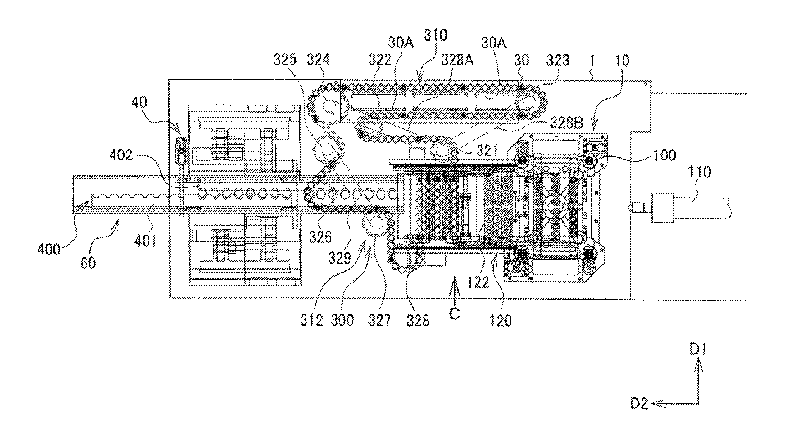
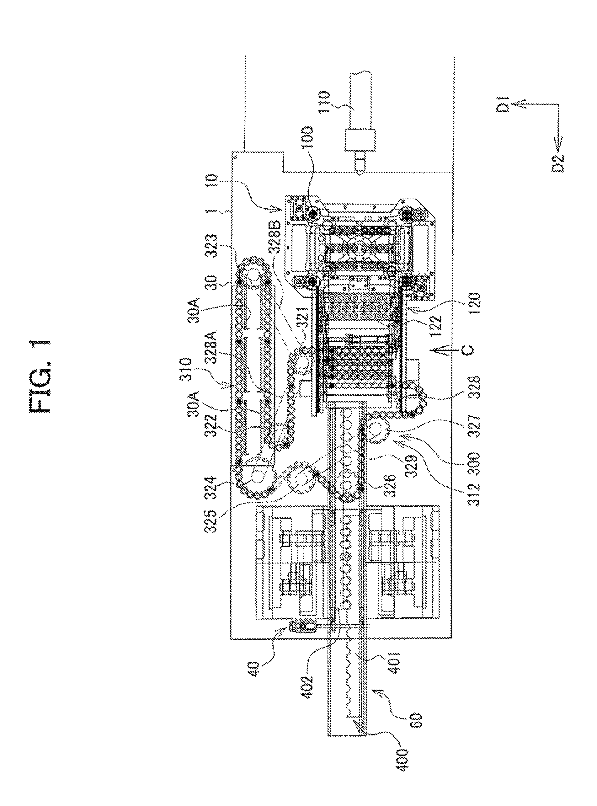
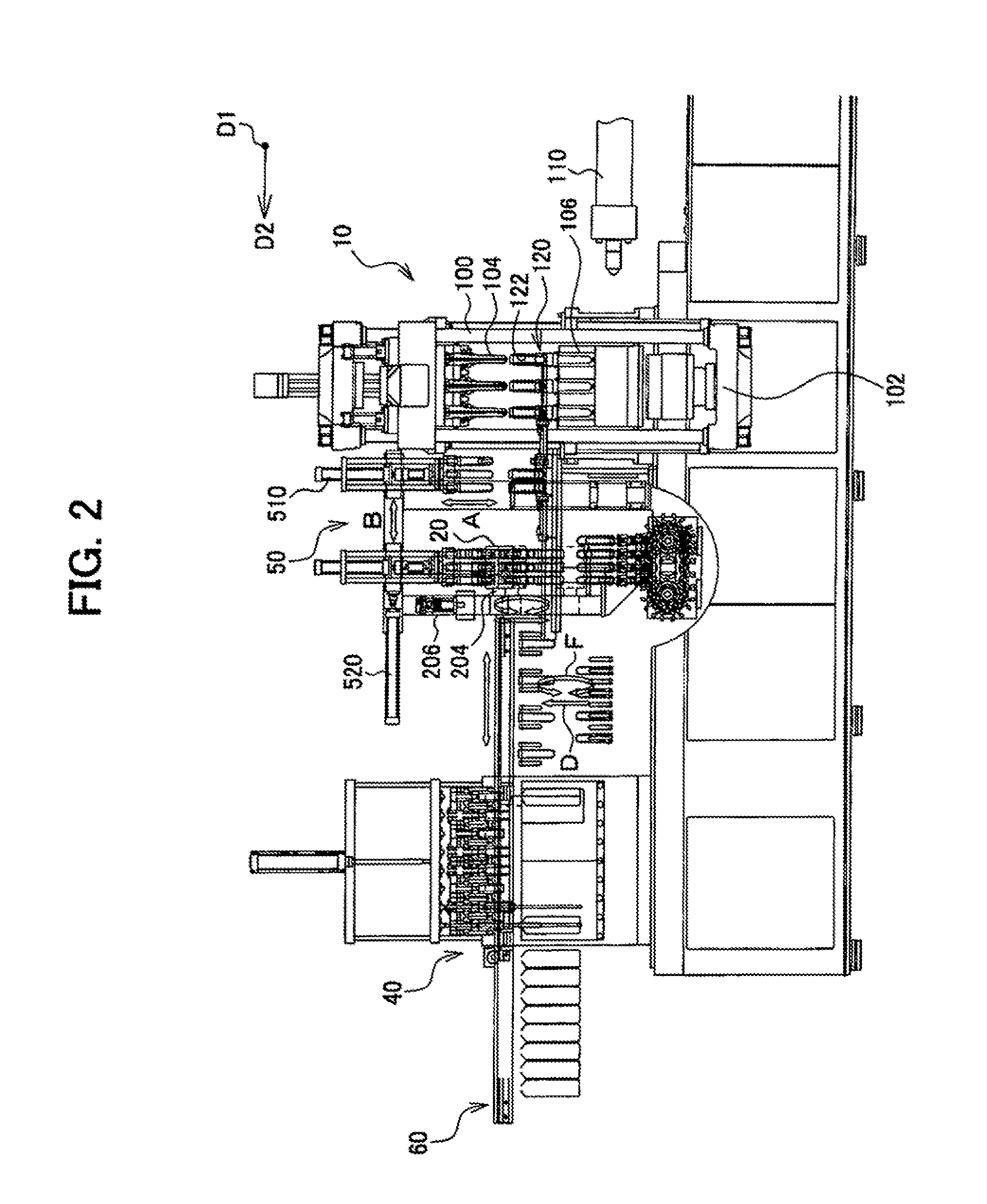
[0090]FIG. 1 is a plan view illustrating an injection stretch blow molding device, and FIG. 2 is a front view illustrating the injection stretch blow molding device. As illustrated in FIGS. 1 and 2, an injection molding section 10, a cooling section 20, a heating section 30, and a blow molding section 40 are provided on a stage 1 of the injection stretch blow molding device.

[0091]Several embodiments of the invention implement a 1.5-stage injection stretch blow molding device that utilizes a 1-stage method in which the injection ...


PUM

PropertyMeasurementUnit
temperatureaaaaaaaaaa
diameteraaaaaaaaaa

Abstract

The injection stretch blow molding device includes an injection molding section that produces N (N is an integer equal to or larger 2) preforms by injection molding, a cooling section that subjects the N preforms transferred from the injection molding section to forced cooling, a heating section that continuously transfers and heats the N cooled preforms, and a blow molding section that subjects the N heated preforms to stretch blow molding in n (n is an integer equal to or larger than 2) operations, the blow molding section simultaneously stretch blow molding M (M=N/n, M is a natural number) preforms among the N preforms into M containers.

Description

CROSS REFERENCE TO RELATED APPLICATION(S)[0001]This application is a continuation of International Patent Application No. PCT / JP2011 / 074273, having an international filing date of Oct. 21, 2011, which designated the United States and which claims priority from Japanese Patent Application No. 2010-238199 filed on Oct. 25, 2010, the entirety of both of which are incorporated herein by reference.BACKGROUND OF THE INVENTION[0002]1. Field of the Invention[0003]The present invention relates to an injection stretch blow molding device and a molded article heating device.[0004]2. Description of the Related Art[0005]A blow molding system may utilize a 2-stage (cold parison) method or a 1-stage (hot parison) method.[0006]According to the 2-stage (cold parison) method, a blow molding system is provided separately from a preform injection molding system, and the preform injection molding operation and the blow molding operation are implemented off-line. A preform (parison) that has been produce...

Claims


Application Information

Patent Timeline
Patent Type & Authority Applications(United States)
IPC IPC(8): B29C49/48
CPCB29C49/06B29C49/12B29C49/4205B65G17/12B29C49/6427B29C49/4823B29C49/064B29C49/6409B29C49/6418B29C49/6472B29C2049/023B29C49/6467B29C49/6465B29C49/648B29C49/681B29C49/68B65G35/06B29K2105/258B29K2067/003B29L2031/712
Inventor YAMAGUCHI, MASAKIANDO, MASATOSHIOGIHARA, SHUICHI
Owner NISSEI ASB MASCH CO LTD
Why Eureka
Try Eureka