Occipital plate systems

a technology of occipital plate and plate, which is applied in the field of orthopedic stabilization systems, can solve the problems of limiting the range of motion, degeneration, disease,

Active Publication Date: 2013-09-12
GLOBUS MEDICAL INC
View PDF8 Cites 25 Cited by
  • Summary
  • Abstract
  • Description
  • Claims
  • Application Information

AI Technical Summary

Benefits of technology

[0004]Various occipital plate systems are provided. In some embodiments, an occipital plate system comprises an occipital plate, the occipital plate having an upper portion and a lower portion, the lower portion including at least one opening for receiving one or more lateral members.
[0005]In other embodiments, an occipital plate system comprises an occipital plate, the occipital plate having an upper portion and a lower portion, the upper portion being tapered such that a thickness of the upper portion is less than a thickness of the lower portion.
[0006]In other embodiments, an occipital plate system comprises an occipital plate having an upper portion and a lower portion, the upper portion comprising a plurality of holes for receiving one or more fasteners therethrough. The system further includes a pair of clamping arms operably attached to the occipital plate, wherein the clamping arms are capable of medial movement in order to clamp the system to vertebral bone.

Problems solved by technology

Many types of spinal irregularities cause pain, limit range of motion, or injure the nervous system within the spinal column.
These irregularities can result from, without limitations, trauma, tumor, disc degeneration, and disease.

Method used


Image

  • Occipital plate systems
  • Occipital plate systems
  • Occipital plate systems

Examples


Embodiment Construction

[0019]Embodiments of the invention will now be described. The following detailed description of the invention is not intended to be illustrative of all embodiments. In describing embodiments of the present invention, specific terminology is employed for the sake of clarity. However, the invention is not intended to be limited to the specific terminology so selected. It is to be understood that each specific element includes all technical equivalents that operate in a similar manner to accomplish a similar purpose.

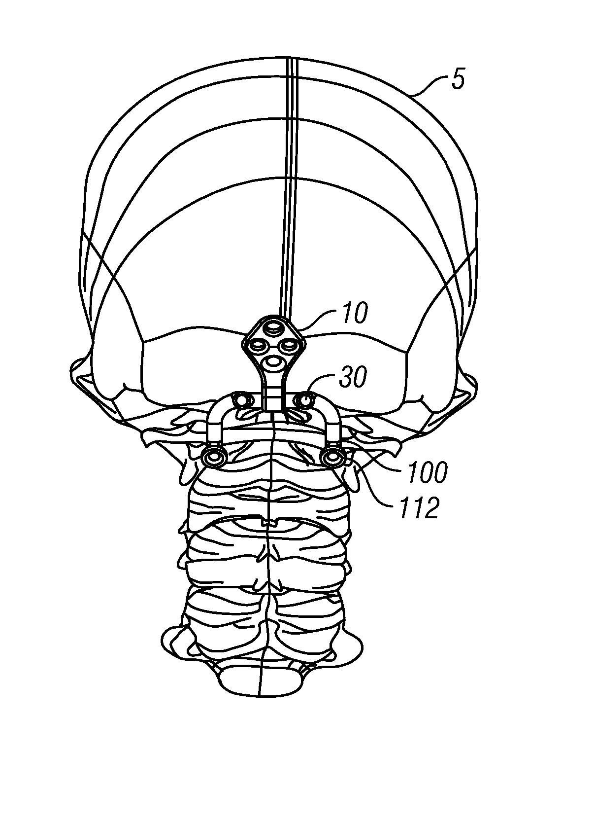
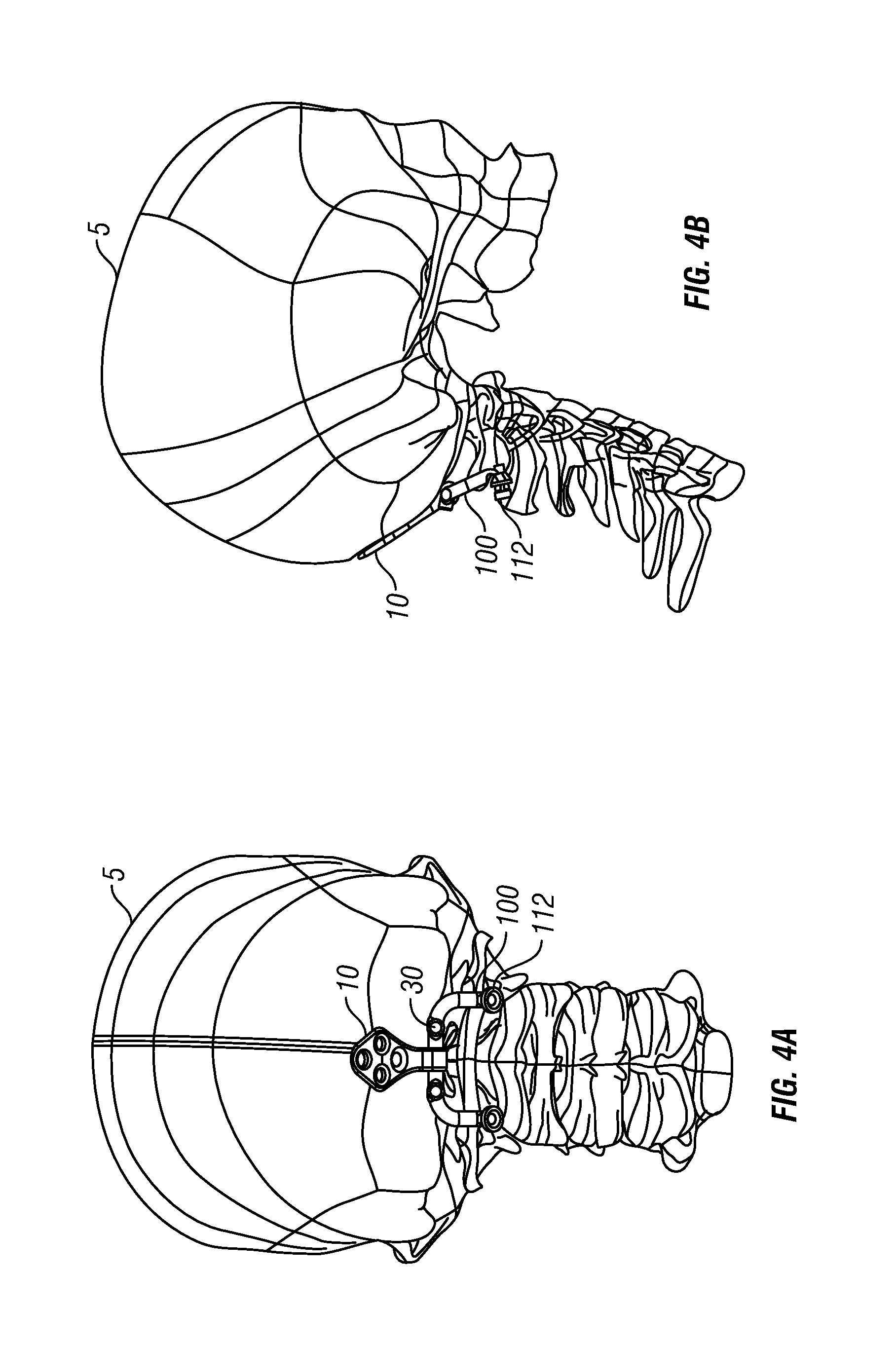
[0020]The present application is generally directed to orthopedic stabilization systems, and in particular, to occipital plate systems. The improved occipital plate systems can include occipital plates operably attached to one or more stabilization rods. In some embodiments, the stabilization rods extend from the skull (e.g., the occipital bone) down to the cervical, thoracic and / or lumbar vertebrae.

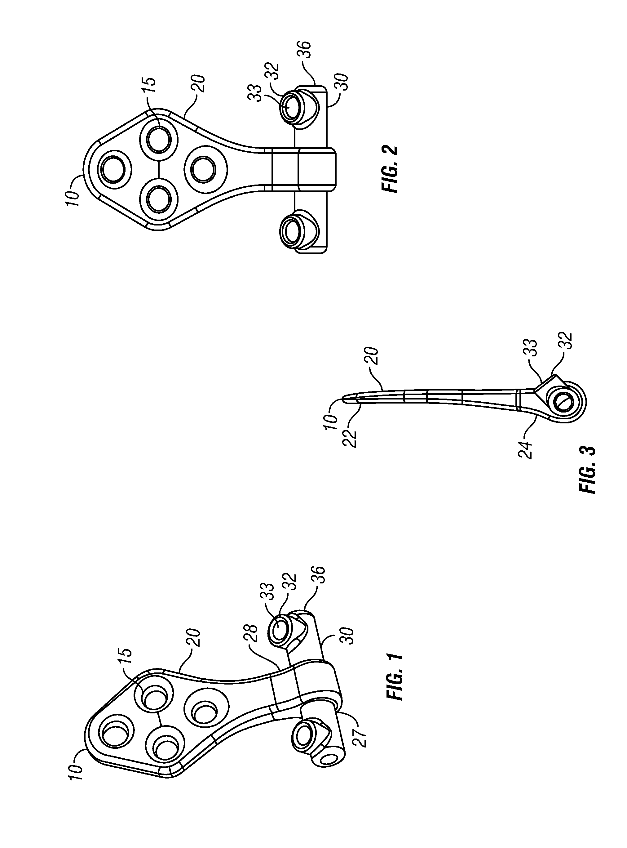
[0021]FIG. 1 is a top perspective view of an improved occipital plate accor...


PUM


Abstract

Occipital plate systems are described. The occipital plate systems can include a novel occipital plate having an upper portion and lower portion. The lower portion can include an opening for receiving one or more lateral members therethrough. The lateral members include top and/or side apertures for receiving lateral connectors that are attached to polyaxial screw receiving members. The occipital plate systems can also include low-profile clamping arms that are operably attached to an occipital plate via an extension member and articulating joint member. The clamping arms, along with tension cables attached intermittently along its length, can be used in addition to or instead of screws and hooks to secure an occipital plate system to vertebrae.

Description

FIELD OF THE INVENTION[0001]The present application is generally directed to orthopedic stabilization systems, and in particular, to occipital plate systems.BACKGROUND OF THE INVENTION[0002]Many types of spinal irregularities cause pain, limit range of motion, or injure the nervous system within the spinal column. These irregularities can result from, without limitations, trauma, tumor, disc degeneration, and disease. Often, these irregularities are treated by immobilizing a portion of the spine. This treatment typically involves affixing a plurality of screws and / or hooks to one or more vertebrae and connecting the screws or hooks to one or more elongate rods that generally extend in the direction of the axis of the spine. Such a system of screws and rods can extend from the skull down to lower vertebral bodies.[0003]Accordingly, there is a need for improved systems involving screws and rods for spinal stabilization.SUMMARY OF THE INVENTION[0004]Various occipital plate systems are ...

Claims


Application Information

Patent Timeline
Patent Type & Authority Applications(United States)
IPC IPC(8): A61B17/80
CPCA61B17/7055A61B17/7053A61B17/7061A61B17/7056A61B17/7047A61B17/70
Inventor BLACK, MICHAEL
Owner GLOBUS MEDICAL INC
Why Eureka
Try Eureka