Utility knife

Inactive Publication Date: 2013-09-19
MILWAUKEE ELECTRIC TOOL CORP
View PDF13 Cites 28 Cited by
  • Summary
  • Abstract
  • Description
  • Claims
  • Application Information

AI Technical Summary

Benefits of technology

[0004]The invention provides, in one aspect, a utility knife. The utility knife includes a frame defining a track and a blade carrier slidably received within the track. A blade is removably coupled to the blade carrier, and an actuator is operably coupled to the blade carrier to facilitate movement of the blade carrier along the track between an extended position and a retracted position. The utility knife also includes a

Problems solved by technology

During use, the blade ma

Method used


Image

  • Utility knife
  • Utility knife
  • Utility knife

Examples


Embodiment Construction

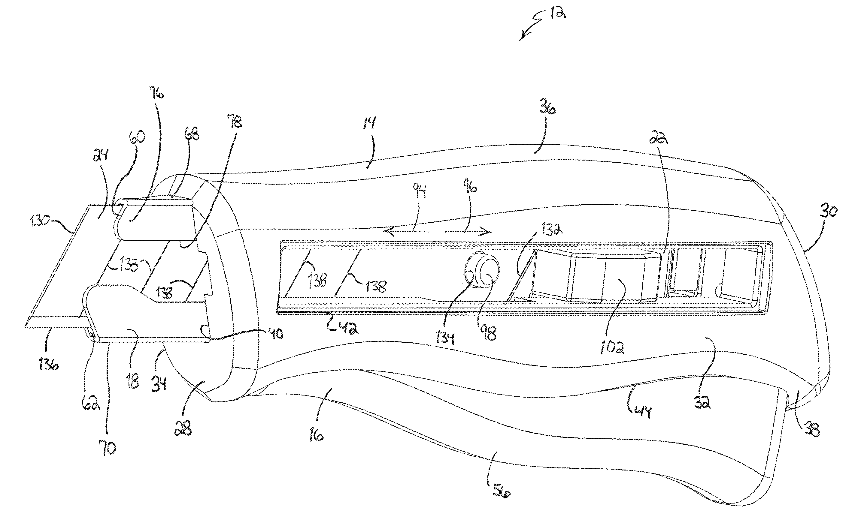
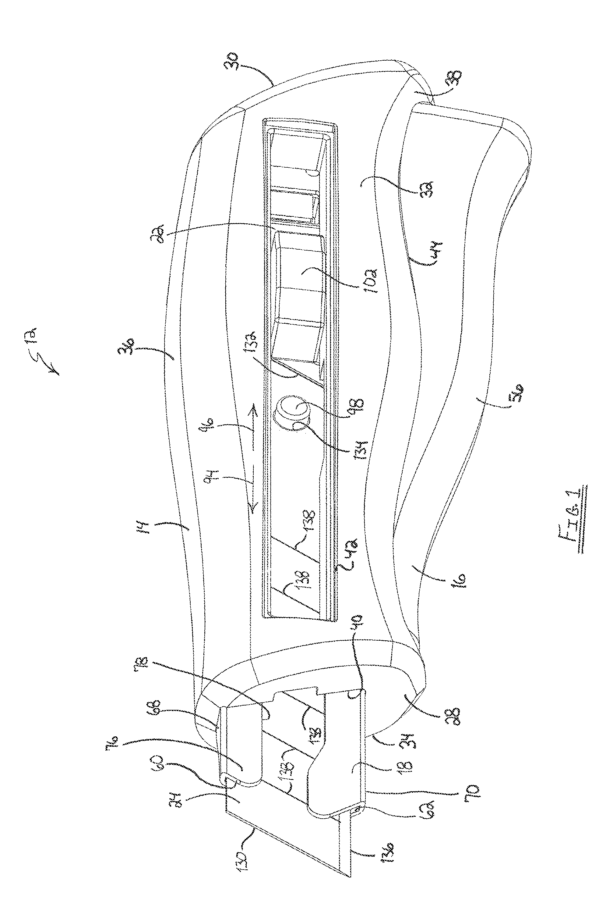
[0049]FIG. 1 illustrates a knife 12, which is a utility knife in the illustrated embodiment. The knife 12 includes a first handle 14, a second handle 16 pivotally coupled to the first handle 14, a frame 18, a locking bar 20 (FIG. 4), a blade carrier 22, and a blade 24.

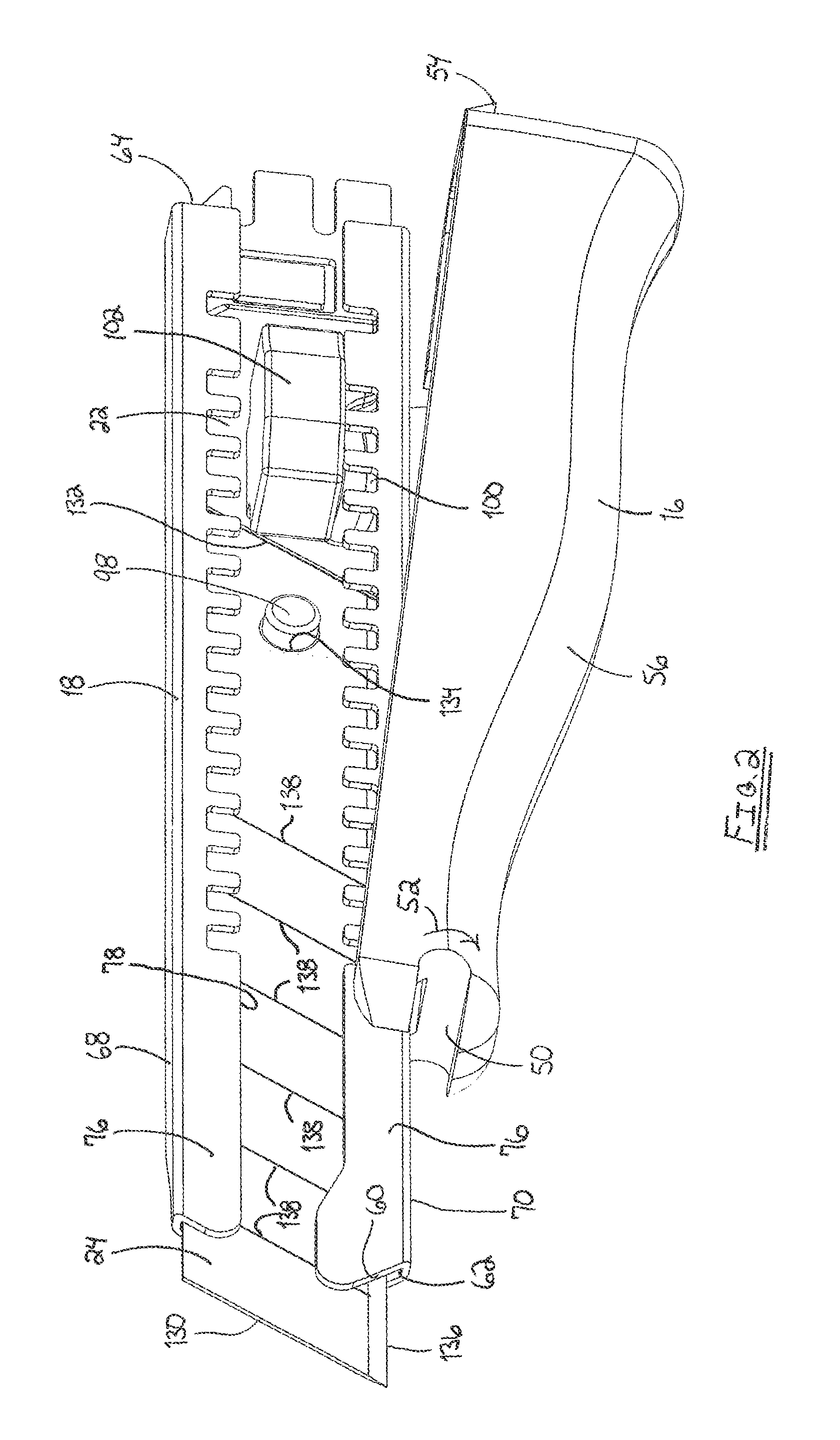
[0050]With continued reference to FIG. 1, the first handle 14 includes a front end 28, back end 30, sidewalls 32 and 34 that extend from the front end 28 to the back end 30, and a top wall 36 and a bottom wall 38 that both extend from the front end 28 to the back end 30. The first handle 14 is generally hollow and includes an opening 40 in the front end 28 through which the frame 18 and the blade 24 extend. An elongated aperture 42 extends through the sidewall 32 between the front end 28 and the back end 30. Also, an elongated aperture 44 extends through the bottom wall 38 between the front end 28 and the back end 30. The second handle 16 pivots through the aperture 44. Referring to FIG. 3, a post 46 extends between th...


PUM


Abstract

A utility knife includes a frame defining a track and a blade carrier slidably received within the track. A blade is removably coupled to the blade carrier, and an actuator is operably coupled to the blade carrier to facilitate movement of the blade carrier along the track between an extended position and a retracted position. The utility knife also includes a first handle portion coupled to the frame and a second handle portion coupled to the first handle portion. The second handle portion is pivotable with respect to the first handle portion and the frame between a first position allowing movement of the blade between the retracted position and the extended position and a second position inhibiting movement of the blade between the retracted position and the extended position.

Description

CROSS-REFERENCE TO RELATED APPLICATIONS[0001]This application claims priority to co-pending U.S. Provisional Patent Application No. 61 / 610,144 filed on Mar. 13, 2012 and to co-pending U.S. Provisional Patent Application No. 61 / 656,196 filed on Jun. 6, 2012, the entire contents of which are incorporated herein by reference.FIELD OF THE INVENTION[0002]The present invention relates to knives and more particularly to utility knives.BACKGROUND OF THE INVENTION[0003]Utility knives typically include a housing, a blade carrier supported by the housing, and a blade coupled to the blade carrier for movement with the blade carrier between an extended position and a retracted position relative to the housing. During use, the blade may become dull or damaged. For some knives, this necessitates replacement of the entire blade. Other utility knives, often referred to as snap knives, incorporate a scored or segmented blade, allowing a user to break off the dull or damaged portion of the blade, to e...

Claims


Application Information

Patent Timeline
IPC IPC(8): B26B1/08
CPCB26B5/002B26B1/08
Inventor WAGNER, ANDREW G.
Owner MILWAUKEE ELECTRIC TOOL CORP
Why Eureka
Try Eureka