Carpentry guide tool for making consistent reveals

a technology of consistent reveals and guide tools, which is applied in the direction of instruments, constructions, building components, etc., can solve the problems of human error in the use of devices, poor aesthetic craftsmanship in the overall project, and no single inventive concept has emerged that addresses all, so as to facilitate the use, and reduce the risk of human error

Inactive Publication Date: 2013-09-19
PARKIN SIMON P
View PDF15 Cites 9 Cited by
  • Summary
  • Abstract
  • Description
  • Claims
  • Application Information

AI Technical Summary

Benefits of technology

[0017]It is an object of the present invention to provide a tool for the creation of reveals and offsets in general carpentry that is both simple to use and simple to manufacture. Simplicity of use is contemplated to mitigate the risk of human error in using the device and simplicity of manufacture is contemplated to make the mass production of the device both efficient and cost effective.
[0018]It is a further object of the present invention to provide a tool for the creation of reveals and offsets in general carpentry wherein the tool is capable of use simultaneously in two orthogonal directions for the accurate measurement of reveals in the corner of a framed threshold. In this sense, the present inventor believes that the present invention will have particular utility in the construction of consistent reveals with regard to the trim and molding around a corner of a framed window, door or other similar threshold.
[0019]It is still yet another object of the present invention to provide a tool for the creation of reveals and offsets in general carpentry wherein the tool is readily portable and convenient to use by a single user simultaneously manipulating the tool to a desired position and measuring the offset for the desired reveal.
[0020]It is still yet another object of the present invention to provide a tool of fixed dimension, completely static in manufacture and unable to be adjusted or altered by a user. The fixed dimension, static manufacture greatly reduces the possibility that human error yields inconsistencies in measurement of a desired reveal around a framed door, window, or other threshold.
[0021]It is still yet another object of the present invention to provide a series of tools serving the aforementioned objects that are of differing gauges in terms of their respective reveals, said series of tools being able to be readily transported and maintained by a carpenter as would any other carpentry tool commonly used in the trade.

Problems solved by technology

Be it difference in measuring convention or just pure human error, the result of varying carpenters working on a single construction product with inconsistent methods of measuring what should be a singular and constant, fixed reveal is inconsistencies in appearance as between thresholds and, thus, poor aesthetic craftsmanship in the overall project.
The state of the prior art in the field of carpentry is such that several developed guides, gauges, or tools meet one or more of the aforementioned needs and desirables, however, no single inventive concept has emerged that addresses all of the aforementioned aspirations.
However, in creating a device that must be adjusted to the predetermined magnitude of reveal, the 336 patent invites human error in the use of the device and, in this sense, is not truly any better than a carpenter using a simple straight ruler to measure the predetermined offset of the reveal.
Further, the 336 patent discloses a guide tool having several varying components, many of which are fairly complex in design so as to make the efficient and affordable manufacture of the tool questionable.
In this sense, the gauge disclosed in the 172 patent suffers from many of the same shortcomings as the 336 patent device, including the invitation of human error in measuring, a perceived higher cost of manufacture and similar difficulties in measuring reveals in the corner of a threshold.
As can be appreciated from the above cited prior art examples, the state of the art favors tools, gauges, and guides that are adjustable and, thus, subject to human error and differences in measurement between individual users.
The opportunity to adjust these devices render the devices no more accurate and precise in the measurement and marking of a reveal than the use of other standard measurement practices known in the art.

Method used


Image

  • Carpentry guide tool for making consistent reveals
  • Carpentry guide tool for making consistent reveals
  • Carpentry guide tool for making consistent reveals

Examples


Embodiment Construction

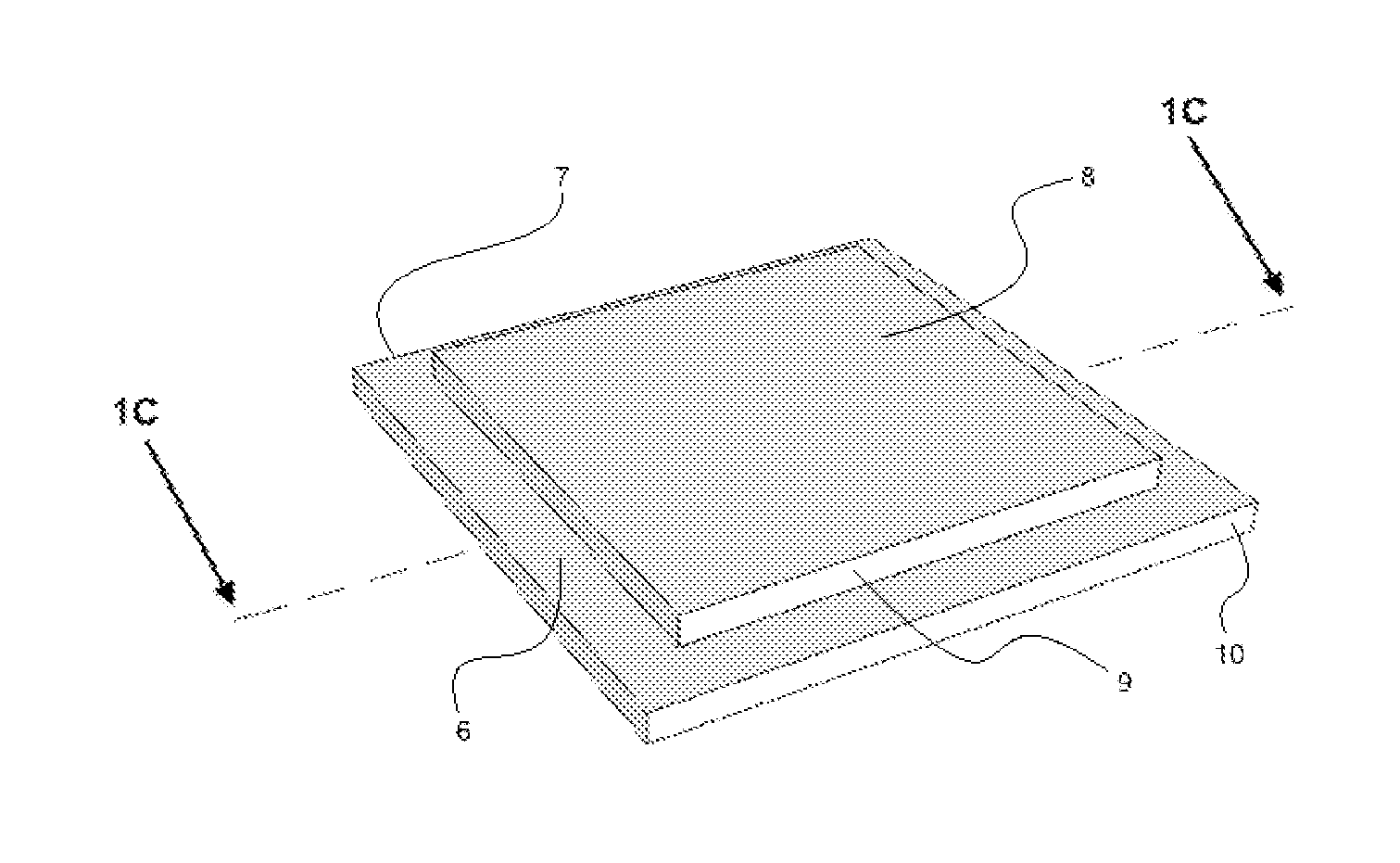
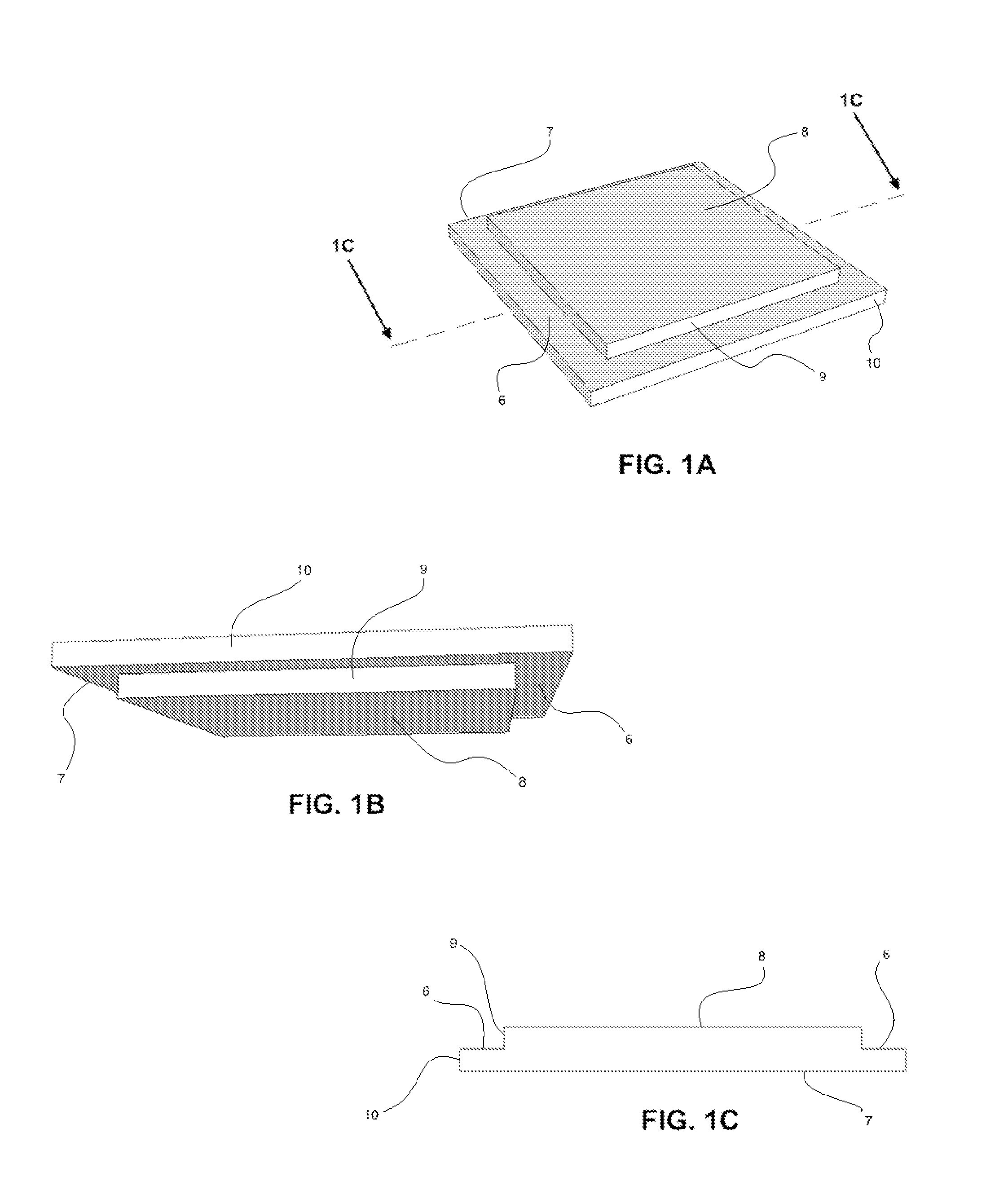
[0032]Referring first to FIG. 1A, there is shown a perspective view of the preferred embodiment from a viewpoint located above the device. Specifically, FIG. 1A shows the inventive concept in its preferred embodiment or best mode as determined by the inventor, said embodiment comprising a first square prism 7 and a second square prism 8, said first prism 7 being an order of magnitude larger than said second prism 8, but in all other respects said first prism 7 and said second prism 8 being congruent. The second prism 8 is arranged in such a way as to have one of its two square faces hidden in constant and flush contact a one of the two square faces of the first prism 7. Further, the first prism 7 and second prism 8 are oriented with regard to one another so that the first prism 7 and second prism 8 are concentric and each planar edge 9 of the second prism 8 is congruent and parallel to each planar edge 10 of the first prism 7. The first prism 7 and second prism 8, via their concentr...


PUM


Abstract

A carpentry guide tool for ensuring precise and accurate measurements with regard to offsets and reveals commonly used in carpentry, particularly in the context of trim and molding around a door or window, is now disclosed. More specifically, the now disclosed carpentry tool is capable of use simultaneously in two orthogonal directions for the accurate measurement of reveals in the corner of a framed threshold and is designed for both ease of use and ease of manufacture. The now disclosed carpentry tool is of fixed dimension and static manufacture, mitigating the possibility that human error yields inconsistencies in measurement. The preferred embodiment is two concentric square prisms of differing sizes wherein every edge of one prism is congruent and parallel to an edge of the second prism, creating a reveal defined by the size differential between the two prisms.

Description

CROSS-REFERENCE TO RELATED APPLICATIONS[0001]Not applicable.STATEMENT REGARDING FEDERALLY SPONSORED RESEARCH OR DEVELOPMENT[0002]Not applicable.REFERENCE TO SEQUENCE LISTING, A TABLE, OR A COMPUTER PROGRAM LISTING COMPACT DISC APPENDIX[0003]Not applicable.BACKGROUND OF THE INVENTION[0004]1. Field of the Invention[0005]The present invention relates generally to tool for use in making accurate and precise measurements in the field of carpentry. More specifically, the present invention relates to an tool having specific use in the accurate and precise measuring or offsets and reveals common in the field of carpentry.[0006]It is not uncommon for many carpenters or framers to be employed on a single carpentry project and, therefore, it is important that the methods and measurements utilized by varying carpenters or framers at work on a single carpentry project be consistent and predictable to ensure the integrity of the carpentry on the particular project as a whole—this is a primary obj...

Claims


Application Information

Patent Timeline
Patent Type & Authority Applications(United States)
IPC IPC(8): E04F21/00
CPCG01B3/30E04F21/00E04F21/003
Inventor PARKIN, SIMON P.
Owner PARKIN SIMON P
Why Eureka
Try Eureka