Ultrasonic flow rate measuring device

a technology of flow rate and measuring device, which is applied in the direction of measurement device, volume/mass flow measurement, instruments, etc., can solve the problems of increasing cost and increasing the number of components, and achieve the effect of high accuracy

Active Publication Date: 2013-09-19
PANASONIC INTELLECTUAL PROPERTY MANAGEMENT CO LTD
View PDF1 Cites 4 Cited by
  • Summary
  • Abstract
  • Description
  • Claims
  • Application Information

AI Technical Summary

Benefits of technology

[0010]In the ultrasonic flow rate measuring device having the above configuration, when the flow path is partitioned into plural sections, it is only necessary to insert the partition plate from the aperture, and it takes hardly any time for assembly. Any protrusions do not exist on insides of the plural flow paths, but the flow rate can be measured with high accuracy.

Problems solved by technology

Therefore, the number of components increases and it takes a long time to assemble multilayer flow path member 100, which results in a problem of a cost increase.

Method used


Image

  • Ultrasonic flow rate measuring device
  • Ultrasonic flow rate measuring device
  • Ultrasonic flow rate measuring device

Examples


Embodiment Construction

[0026]Hereinafter, an embodiment of the present invention will be described with reference to the drawings. However, the present invention is not limited to the embodiment.

EXEMPLARY EMBODIMENT

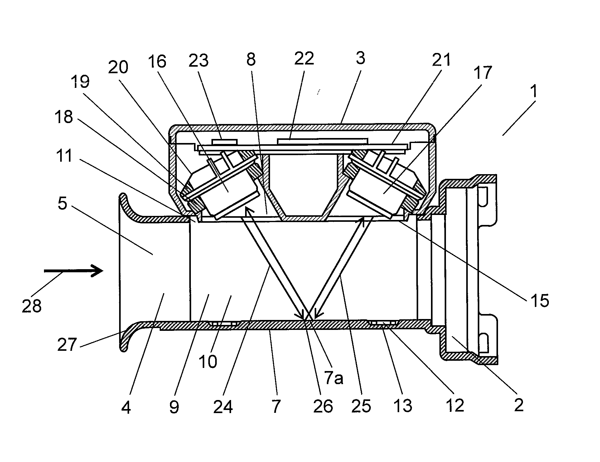
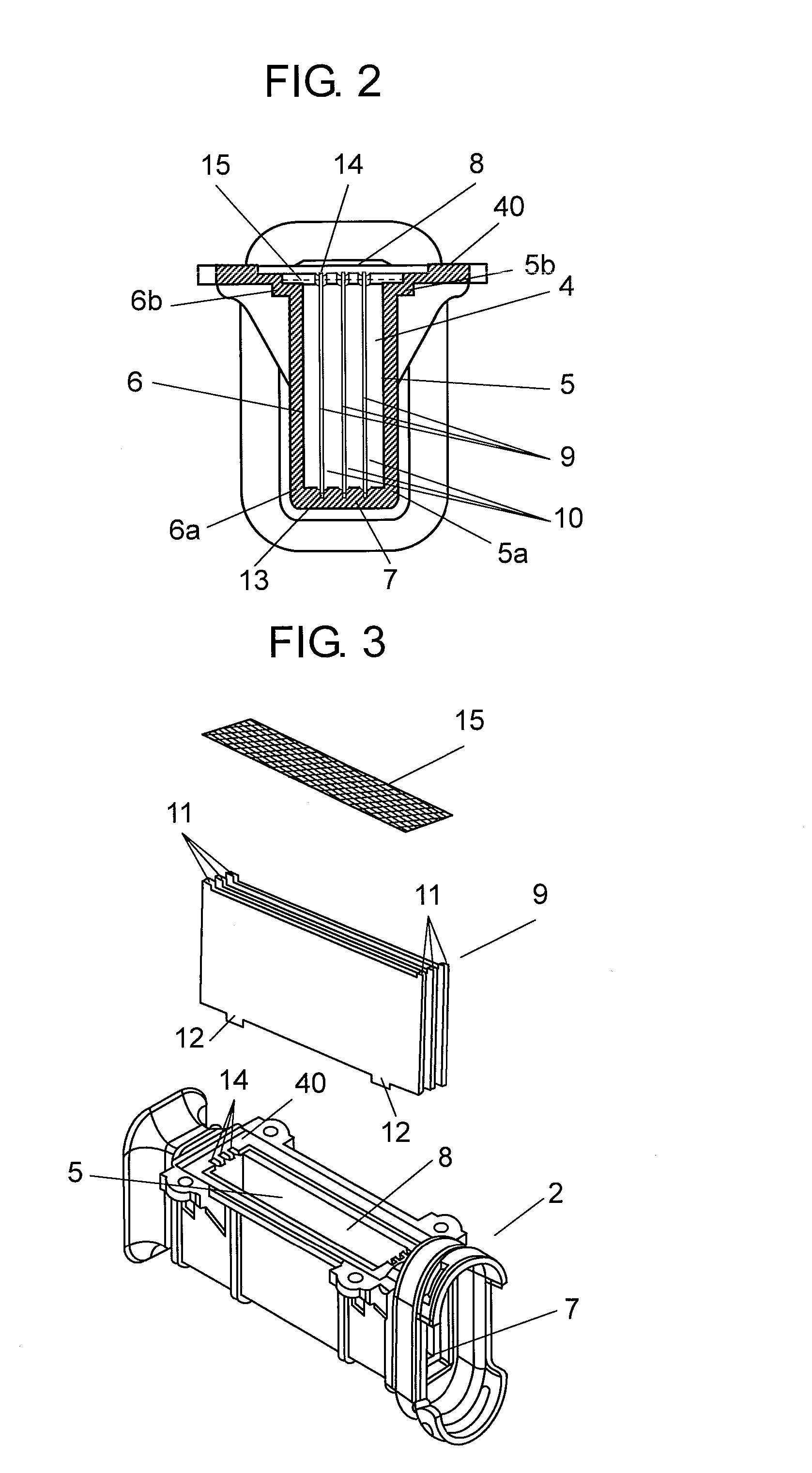
[0027]FIG. 1 is a sectional view illustrating a configuration of an ultrasonic flow rate measuring device according to an embodiment of the present invention, FIG. 2 is a side view illustrating a flow path block of the ultrasonic flow rate measuring device of the embodiment, and FIG. 3 is an exploded perspective view illustrating the flow path block of the ultrasonic flow rate measuring device of the embodiment.

[0028]As illustrated in FIGS. 1 to 3, ultrasonic flow rate measuring device 1 includes flow path block 2 and sensor block 3. Rectangular flow path 4 is formed by first sidewall 5 that is provided along arrow 28 indicating a flow direction of a target fluid, second sidewall 6 that is disposed facing first sidewall 5, bottom plate 7, upper wall unit 40, and aperture 8. The target fluid of ...


PUM


Abstract

An ultrasonic flow rate measuring device includes a flow path, a partition plate that is inserted from an aperture to partition the flow path into plural sections, an ultrasound transmission body, plural ultrasonic transducers that are provided in positions facing a bottom plate such that an ultrasonic wave transmitted from one of the ultrasonic transducers through the ultrasound transmission body is reflected by the bottom plate and received by the other ultrasonic transducer, a measurement circuit that measures an ultrasonic propagation time between the plurality of the ultrasonic transducers; and a calculation circuit that obtains a flow rate of the target fluid based on a signal from the measurement circuit.

Description

TECHNICAL FIELD[0001]The present invention relates to an ultrasonic flow rate measuring device.BACKGROUND ART[0002]In a conventional ultrasonic flow rate measuring device, plural partition plates that partition a flow path are latched in slits provided in both side plates of the flow path in order to construct a multilayer flow path. Plural flat flow paths are formed (for example, see PTL 1).[0003]FIG. 10 is an overall perspective view of a conventional ultrasonic flow rate measuring device described in PTL 1, FIG. 11 is a sectional view in a direction 11-11 when the ultrasonic flow rate measuring device in FIG. 10 is cut by a plane A, FIG. 12 is an exploded perspective view of a multilayer flow path member of the ultrasonic flow rate measuring device, and FIG. 13 is a sectional view in a direction 13-13 when a side plate in FIG. 12 is cut by a plane B. As illustrated in FIGS. 10 to 13, a multilayer flow path member 100 includes partition plates 103 that partition measurement flow p...

Claims


Application Information

Patent Timeline
Patent Type & Authority Applications(United States)
IPC IPC(8): G01F1/66
CPCG01F1/66G01F1/667G01F1/662
Inventor OZAKI, YUKINORIFUJII, YUJISATOU, MASATOGOTOU, HIROKAZUWATANABE, AOI
Owner PANASONIC INTELLECTUAL PROPERTY MANAGEMENT CO LTD
Why Eureka
Try Eureka