Fast response fluid temperature control system

a fluid temperature control and fast response technology, applied in process and machine control, lighting and heating equipment, instruments, etc., can solve problems such as limiting the power load of such point-of-use systems

Inactive Publication Date: 2013-09-19
APPLIED MATERIALS INC
View PDF6 Cites 19 Cited by
  • Summary
  • Abstract
  • Description
  • Claims
  • Application Information

AI Technical Summary

Benefits of technology

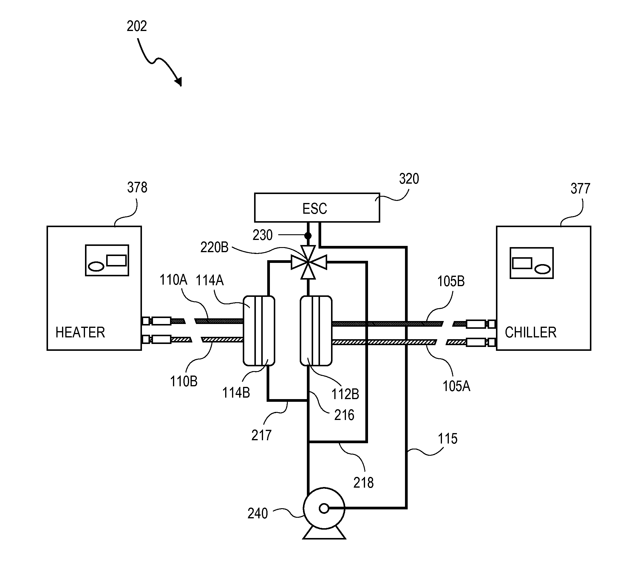
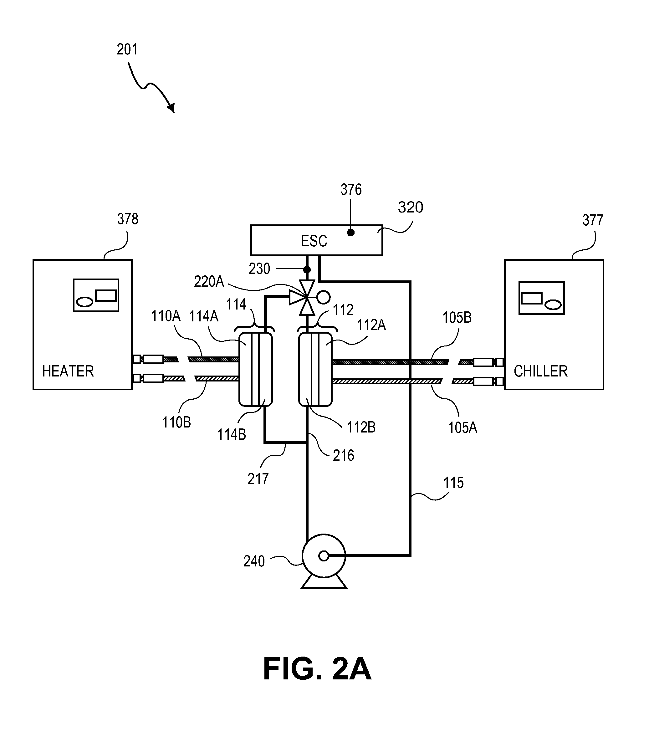
[0007]In embodiments, multiple supply lines and multiple heat transfer fluid reservoirs (e.g., hot and cold) are coupled to the local loop with multiple heat exchangers having their secondary sides configured in parallel. In each branch of the local loop there is a 2-way that is co

Problems solved by technology

Long line lengths in a heat transfer fluid loop, and the large heat transfer fluid volumes associated with such long line lengths are detrimental to temperature control response tim

Method used


Image

  • Fast response fluid temperature control system
  • Fast response fluid temperature control system
  • Fast response fluid temperature control system

Examples


Embodiment Construction

[0019]In the following description, numerous details are set forth. It will be apparent, however, to one skilled in the art, that the present invention may be practiced without these specific details. In some instances, well-known methods and devices are shown in block diagram form, rather than in detail, to avoid obscuring the present invention. Reference throughout this specification to “an embodiment” means that a particular feature, structure, function, or characteristic described in connection with the embodiment is included in at least one embodiment of the invention. Thus, the appearances of the phrase “in an embodiment” in various places throughout this specification are not necessarily referring to the same embodiment of the invention. Furthermore, the particular features, structures, functions, or characteristics may be combined in any suitable manner in one or more embodiments. For example, a first embodiment may be combined with a second embodiment anywhere the two embod...


PUM

PropertyMeasurementUnit
Temperatureaaaaaaaaaa

Abstract

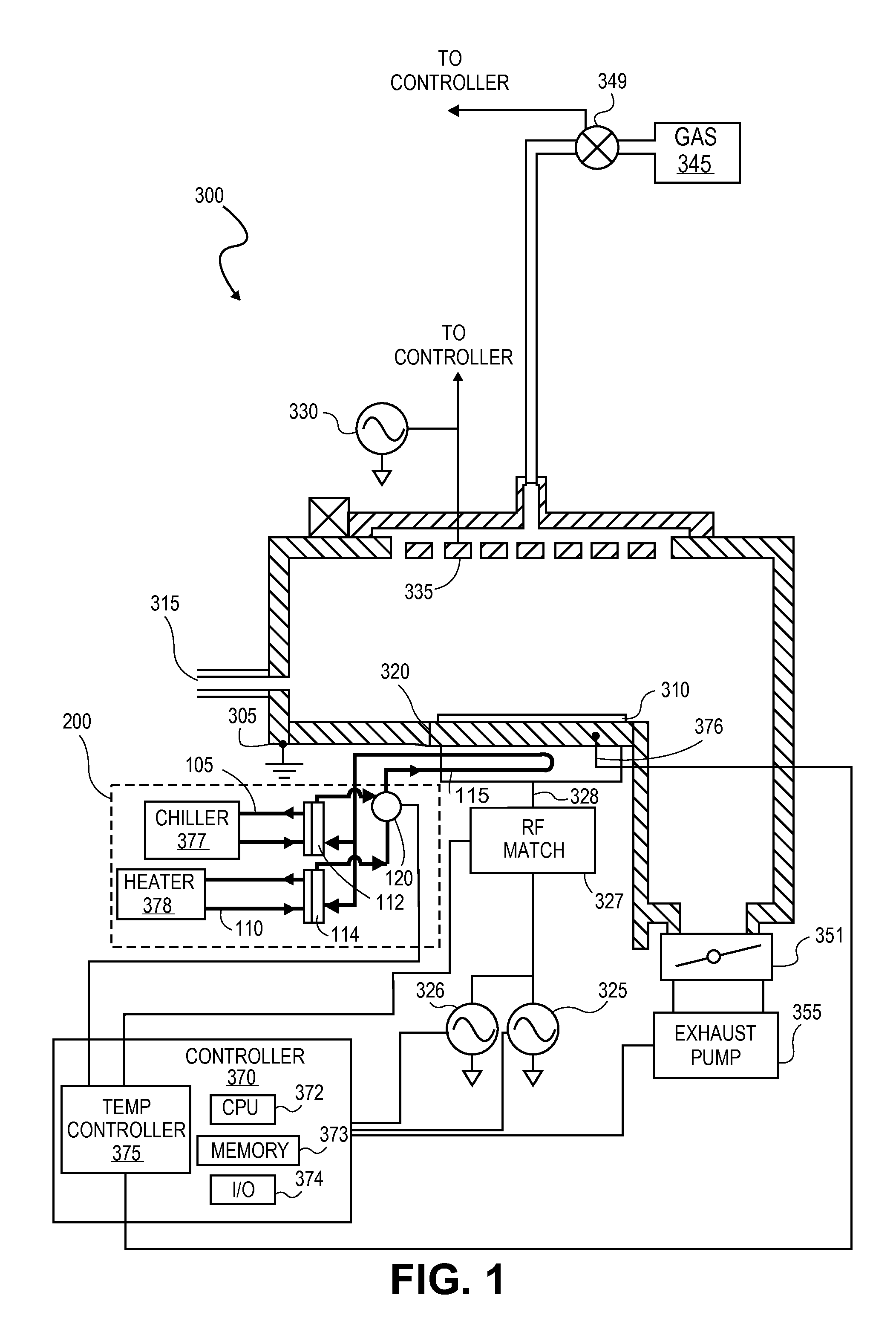
A plasma processing apparatus and method to control a temperature of a chamber component therein. A process chamber may include a temperature controlled chamber component and at least one remote heat transfer fluid loop comprising a first heat exchanger having a primary side in fluid communication with a heat sink or heat source, and a local heat transfer fluid loop placing the chamber component in fluid communication with a secondary side of the first heat exchanger. The local loop may be of significantly smaller fluid volume than the remote loop(s) and circulated to provide thermal load of uniform temperature. Temperature control of heat transfer fluid in the local loop and temperature control of the chamber component may be implemented with a cascaded control algorithm.

Description

TECHNICAL FIELD[0001]Embodiments of the present invention generally relate to plasma processing equipment, and more particularly to methods of controlling chamber component temperatures during processing of a workpiece with a plasma processing chamber.BACKGROUND[0002]In a plasma processing chamber, such as a plasma etch or plasma deposition chamber, the temperature of a chamber component is often an important parameter to control during a process. For example, a temperature of a substrate holder, commonly called a chuck or pedestal, may be controlled to heat / cool a workpiece to various controlled temperatures during the process recipe (e.g., to control an etch rate). Similarly, a temperature of a showerhead / upper electrode, chamber liner, baffle, process kit, or other component may also be controlled during the process recipe to influence the processing. Conventionally, a heat sink and / or heat source is coupled to the processing chamber to maintain the temperature of a chamber compo...

Claims


Application Information

Patent Timeline
IPC IPC(8): F28F27/02F28F27/00B05C11/00F28D15/00
CPCB05C11/00H01J37/32724H01J37/32522G05D23/00G05D23/1393
Inventor BUCHBERGER, DOUGLAS A.NEVIL, SHANERAMASWAMY, KARTIKCOLLINS, KENNETHFOVELL, RICHARD
Owner APPLIED MATERIALS INC
Why Eureka
Try Eureka