
Punch assembly with quick attach punch point and stripper plate removably secure thereon

Active Publication Date: 2013-09-19
MATE PRECISION TOOLING
View PDF5 Cites 8 Cited by
  • Summary
  • Abstract
  • Description
  • Claims
  • Application Information

AI Technical Summary

Benefits of technology

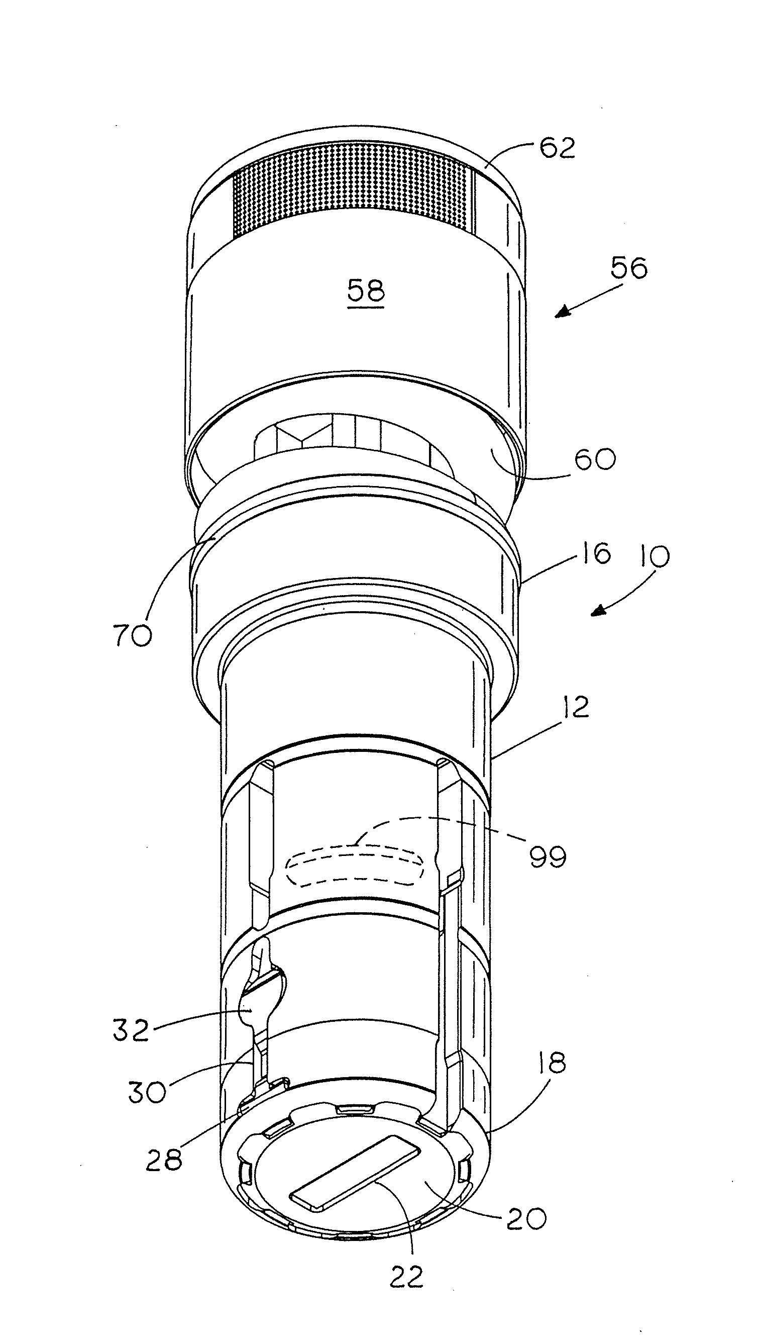
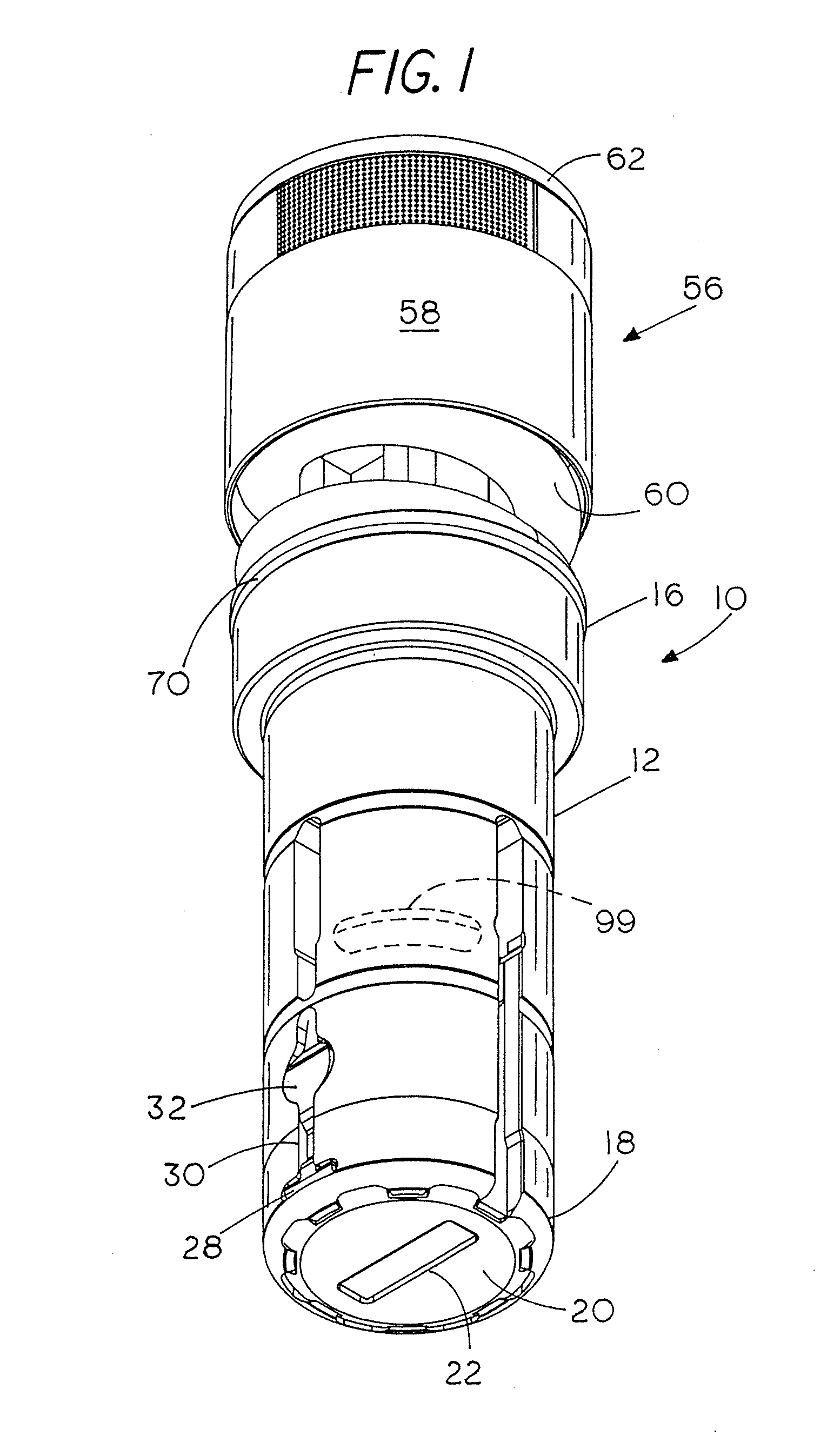
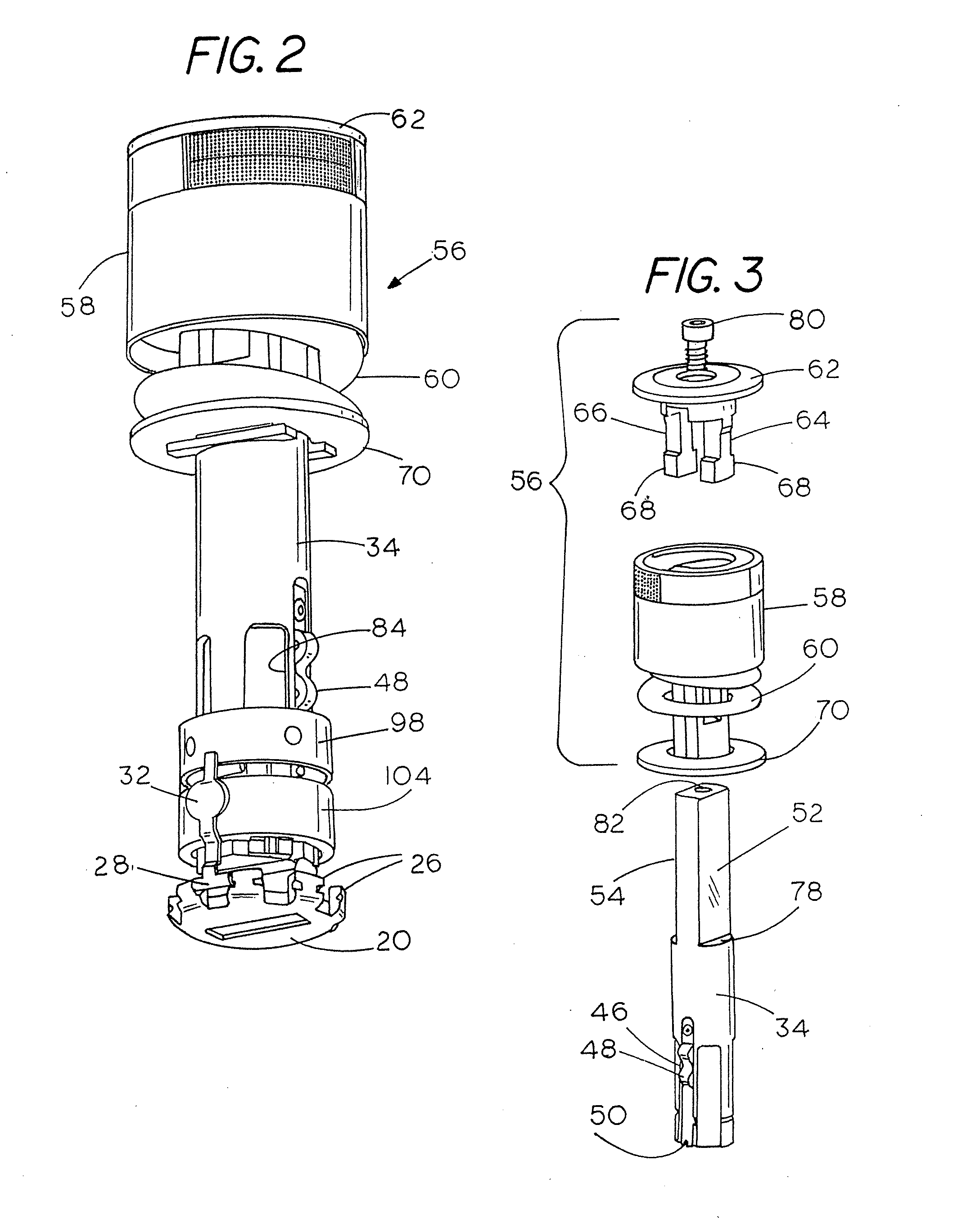
The present invention is a punch assembly for a turret punch press that allows for easy replacement of the punch insert. The assembly includes a cylindrical punch guide with a cyclically movable punch driver. The punch driver has a canister assembly with a compression spring to bias it in a retracted position. The punch driver has guideways with locking sliders and a lock collar for easy engagement and disengagement with the punch insert. A metal stripper member is clamped to the punch guide and has an aperture shaped to match the punch point of the punch insert. The stripper member can be easily unclamped and reclamped without special tools. Overall, the invention simplifies the process of replacing the punch insert and improves the efficiency of the turret punch press.

Problems solved by technology

Notwithstanding the use of such a high-grade and relatively expensive punch point insert, after a period of use in punching holes through sheet steel and other metals, it becomes necessary to replace the punch point insert with a new or resharpened one.

Method used


Image

  • Punch assembly with quick attach punch point and stripper plate removably secure thereon
  • Punch assembly with quick attach punch point and stripper plate removably secure thereon
  • Punch assembly with quick attach punch point and stripper plate removably secure thereon

Examples


Embodiment Construction

[0025]This description of the preferred embodiments is intended to be read in connection with the accompanying drawings, which are to be considered part of the entire written description of this invention. In the description, relative terms such as “lower”, “upper”, “horizontal”, “vertical”, “above”, “below”, “up”, “down”, “top” and “bottom” as well as derivatives thereof (e.g., “horizontally”, “downwardly”, “upwardly”, etc.) should be construed to refer to the orientation as then described or as shown in the drawings under discussion. These relative terms are for convenience of description and do not require that the apparatus be constructed or operated in a particular orientation. Terms such as “connected”, “connecting”, “attached”, “attaching”, “join” and “joining” are used interchangeably and refer to one structure or surface being secured to another structure or surface or integrally fabricated in one piece, unless expressively described otherwise.

[0026]As shown in FIG. 1, the ...


PUM

PropertyMeasurementUnit
longitudinal displacementaaaaaaaaaa
inner diameteraaaaaaaaaa
shapeaaaaaaaaaa

Abstract

A punch assembly for a turret punch press having a two piece reciprocally movable punch member that has a punch point insert removably attached to a punch driver that allows replacement of the punch point insert without the need to extract the punch member from its punch guide. A locking assembly comprising four vertical guideways containing slider strips for coupling the punch point insert to the punch driver ensures precision registration of the punch point insert with its driver.

Description

BACKGROUND OF THE INVENTION[0001]I. Field of the Invention[0002]This invention relates generally to high speed metal punching equipment suited for installation in a turret-style punch press and more particularly to the design of a punch assembly used in such equipment that allows for quick removal of a worn punch insert from the punch guide for refurbishment and return or replacement.[0003]II. Discussion of the Prior Art[0004]To provide increased mean-time-to-repair of punch assemblies used in high-speed CNC controlled turret punch presses, it has proved expedient to employ a high-grade high speed steel insert such as American National Standards Institute M2 steel punch point insert affixed to the end of a lower cost steel punch driver to reduce cost of the punch press assembly. Notwithstanding the use of such a high-grade and relatively expensive punch point insert, after a period of use in punching holes through sheet steel and other metals, it becomes necessary to replace the pun...

Claims


Application Information

Patent Timeline
Patent Type & Authority Applications(United States)
IPC IPC(8): G06K1/00
CPCB21D28/246Y10T83/9428Y10T83/9476
Inventor THOMSON, STEVE H.
Owner MATE PRECISION TOOLING
Learn More