
Fracture fixation plate, system and methods of use

Active Publication Date: 2013-09-19
SKELETAL HLDG LLC
View PDF31 Cites 43 Cited by
  • Summary
  • Abstract
  • Description
  • Claims
  • Application Information

AI Technical Summary

Benefits of technology

The patent aims to address the limitations of existing devices by providing innovative features to achieve better fixation of plates to osteoporotic bones, improved visualization of fracture lines, intraoperative adjustability for better contact with the bone, reduction of risks of tendon rupture, improved fixation of small fragments, improved targeting and fixation of specific bone fragments, and reduction of the time required for surgery.

Problems solved by technology

While many existing volar plates are effective, in many instances they do not provide the means for: a.) good visualization of the fracture; b.) achieving good contact between the plate and the bone; c.) the need to target particular bone fragments; d.) the fixation of small volar marginal fragments and e.) accommodating for conditions such as morbidity of the patient in the form of osteoporotic diaphyseal
bone. Furthermore, in a small but significant number of cases, known fracture fixation plates and / or the fasteners attached thereto can impinge upon flexor and / or extensor tendons, resulting in post-operative tendon injury or ru

Method used


Image

  • Fracture fixation plate, system and methods of use
  • Fracture fixation plate, system and methods of use
  • Fracture fixation plate, system and methods of use

Examples


Embodiment Construction

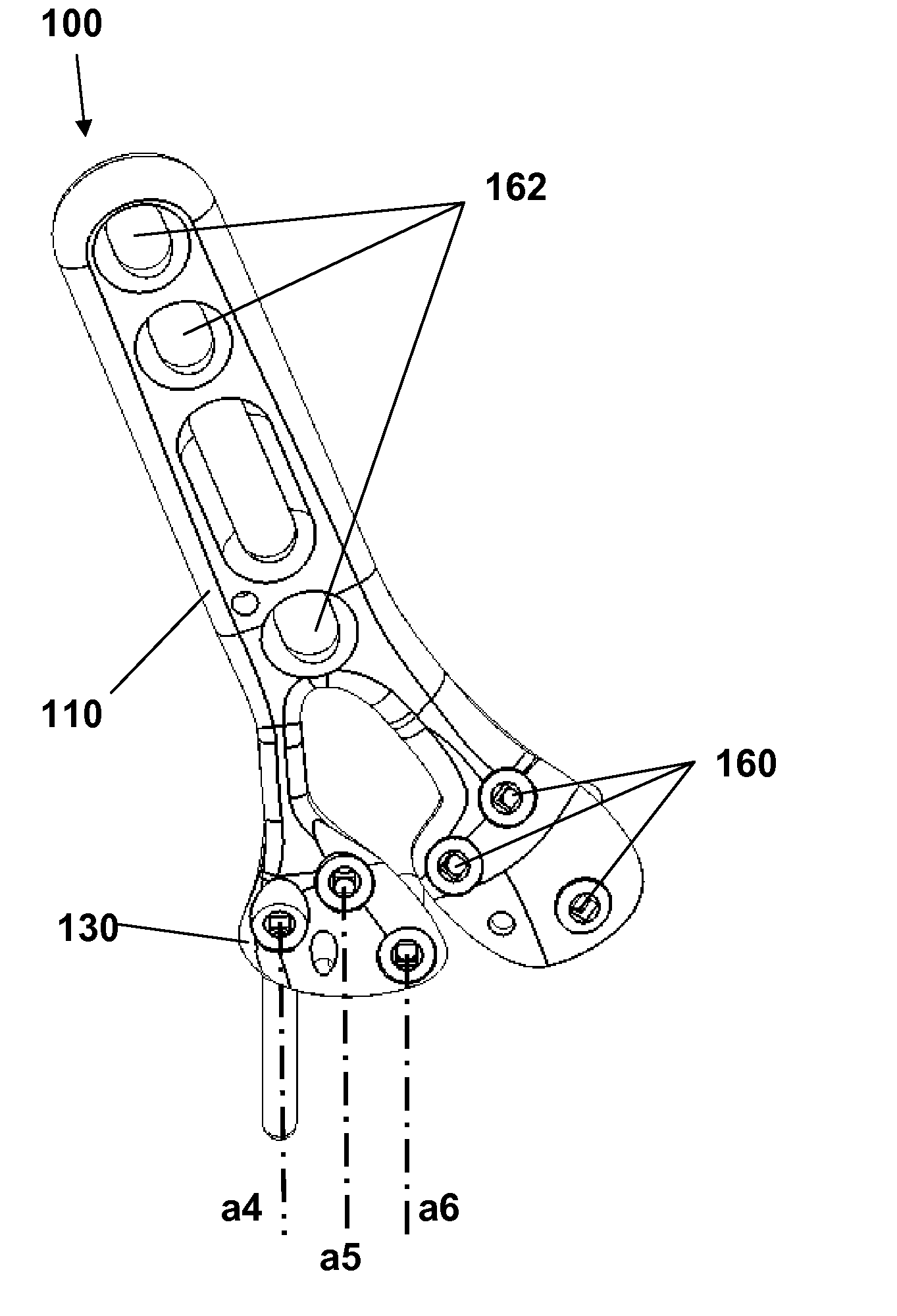
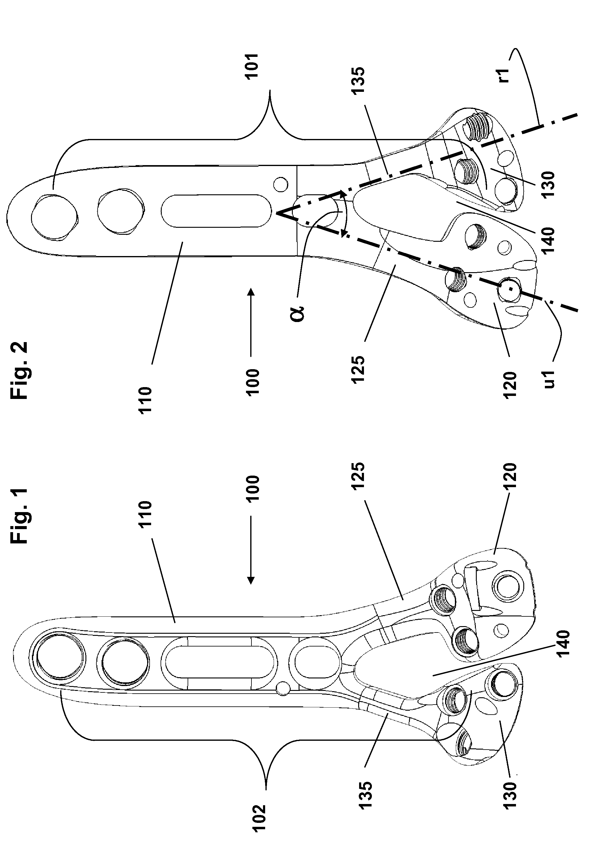
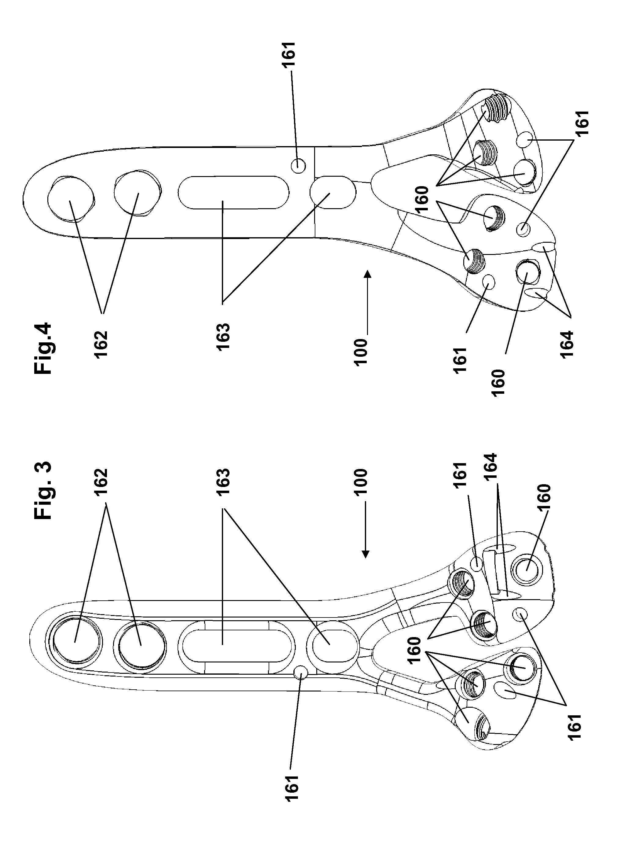
[0047]Referring to FIGS. 1 and 2, a generally “Y” shaped volar fracture fixation plate 100 is shown having a bone contacting surface 101 and an opposite surface 102, a straight or slightly curving elongated body portion 110 having a proximal end and a distal end and a plurality of independently adjustable head portions 120, 130. The plurality of head portions are angled relative to the body portion 110 about ulnar lateral axis u1 and radial lateral axis r1 that diverge distally at an angle α not less than 20 degrees and not greater than 45 degrees. In one embodiment of the present invention, for use as a volar radius fixation plate, the plurality of head portions are embodied as an ulnar head portion 120 and a radial head portion 130. Head portions 120 and 130 are independently connected to body portion 110, respectively, by ulnar neck portion 125 and radial neck portion 135 which branch out angularly from the distal end of body portion 110 and are independently adjustable. Body por...


PUM


Abstract

A plate for fracture fixation, a system and methods are provided including a plurality of individually adjustable heads and various features and accessories to achieve: a.) superior fixation of the plate to osteoporotic diaphyseal bone; b.) improved visualization of the fracture line; c.) intraoperative adjustability to achieve better contact of the plate and the bone; d.) reduced risk of post-surgery tendon rupture; d.) improved fixation of small volar marginal fragments; e.) improved targeting and fixing of particular fractured bone fragments and, f.) reduced surgical operation time.

Description

CLAIM OF PRIORITY[0001]This application is being filed as a non-provisional patent application under 35 U.S.C. §111(b) and 37 CFR §1.53(c). This application is a continuation-in-part of application Ser. No. 13 / 366,886 filed on Feb. 6, 2012 and claims priority under 35 U.S.C. §111(e) to U.S. provisional patent application Ser. No. 61 / 531,485 filed on Sep. 6, 2011; Ser. No. 61 / 536,316 filed on Sep. 19, 2011 and Ser. No. 61 / 595,986 filed on. Feb. 7, 2012, the contents of which are incorporated herein by reference.FIELD OF INVENTION[0002]The invention relates generally to the fixation of bone fractures and in particular to plates for the volar fixation of fractures of the distal radius.BACKGROUND OF THE INVENTION[0003]Fracture fixation plates for the distal radius are known in the art. In particular, volar fracture fixation plates for the treatment of the Colles' fracture are frequently used. While many existing volar plates are effective, in many instances they do not provide the means...

Claims


Application Information

Patent Timeline
IPC IPC(8): A61B17/80
CPCA61B17/1728A61B17/8057A61B17/8061A61B17/808A61B17/8085A61B17/80A61B17/863A61B17/864A61B17/8863A61B2019/307A61B2019/5466A61B17/809A61B17/8004A61B2090/037A61B2090/3966
Inventor ORBAY, JORGE L.NORMAN, THOMAS H.SALCEDO, JUAN
Owner SKELETAL HLDG LLC
Learn More