Methods of forming high-porosity fractures in weakly consolidated or unconsolidated formations

Active Publication Date: 2013-09-26
HALLIBURTON ENERGY SERVICES INC
View PDF6 Cites 35 Cited by
  • Summary
  • Abstract
  • Description
  • Claims
  • Application Information

AI Technical Summary

Benefits of technology

[0008]Some embodiments of the present invention provide methods of fracturing a subterranean formation penetrated by a well bore, that include the steps of placing a fracturing fluid comprising a first stabilizing substance into the subterranean formation at or above a pressure sufficient to create or enhance at least one fracture in the subterranean formation; placing a treatment fluid comprising a gel carrier fluid, degradable solid-free gel bodies, and solids-laden gel bodies into the fracture such that the solids-free gel bodies and the solids-laden gel bodies form multiple packs within the fracture; allowing the pressure within the subterranean formation to fall below a pressure sufficient to create or enhance at least one fracture in the subterranean formation; and, breaking the gel carrier fluid and allowing the solid-free gel bodies to degrade to create a high porosity propped fracture formed of the solids-laden gel bodies wherein the propped fracture has a porosity of at least about 40%.
[0009]Other embodiments of the present invention prov

Problems solved by technology

Unfortunately, in such traditional operations, when fractures close upon the proppant particulates they can crush or become compacted, potentially forming non-permeable or low permeability masses within the fracture rather than desirable high permeability masses; such low permeability masses may choke the flow path of the fluids within the formation.
Furthermore, the proppant particulates may become embedded in particularly soft formations, negatively impacting production.
While this concept of partial monolayer fracturing has been investigated in the industry, the concept has not been successfully applied for a number of reasons.
One problem is that successful placement of a partial monolayer of proppant particulates presents unique challenges in the re

Method used


Image

  • Methods of forming high-porosity fractures in weakly consolidated or unconsolidated formations
  • Methods of forming high-porosity fractures in weakly consolidated or unconsolidated formations
  • Methods of forming high-porosity fractures in weakly consolidated or unconsolidated formations

Examples


Example

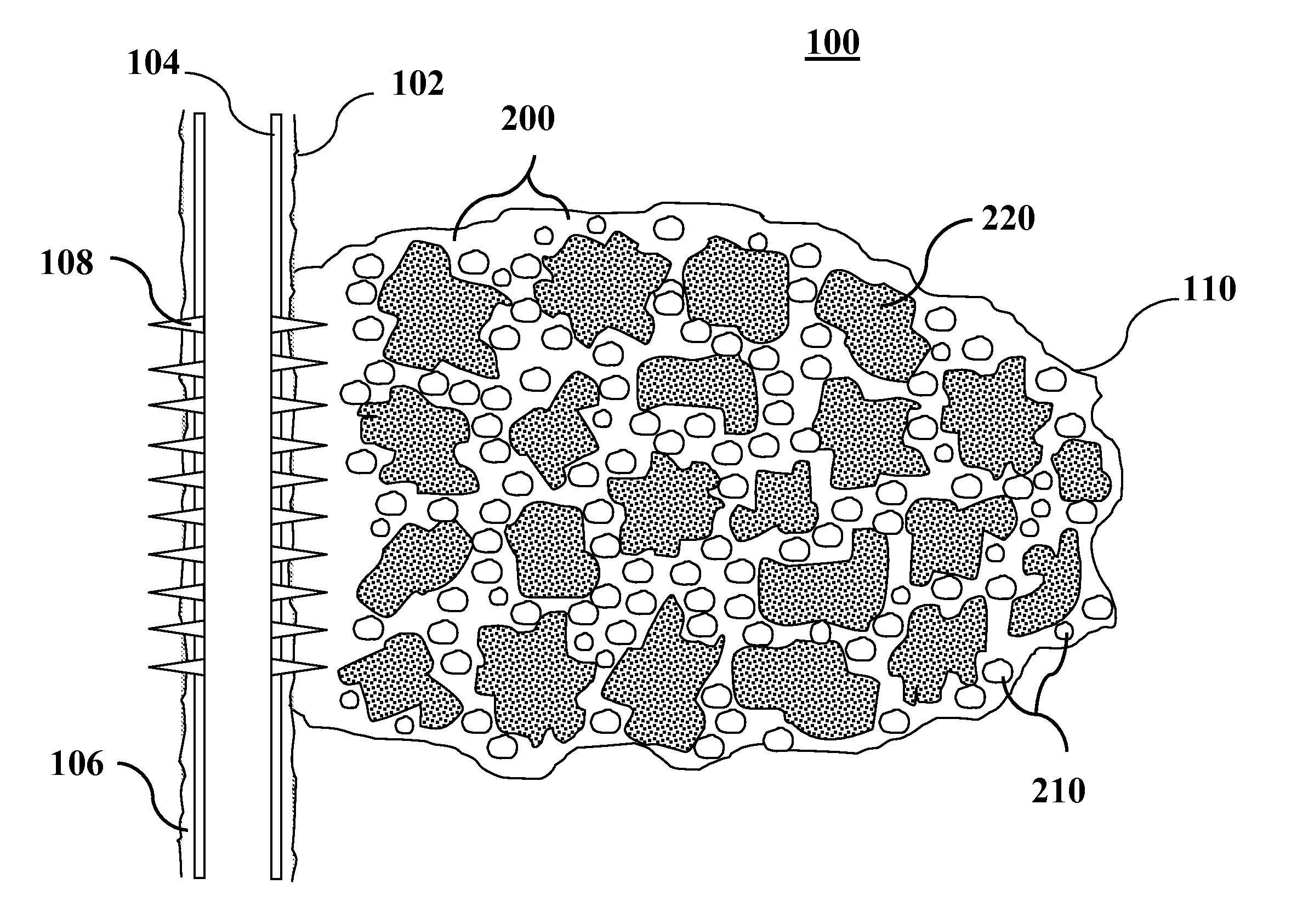
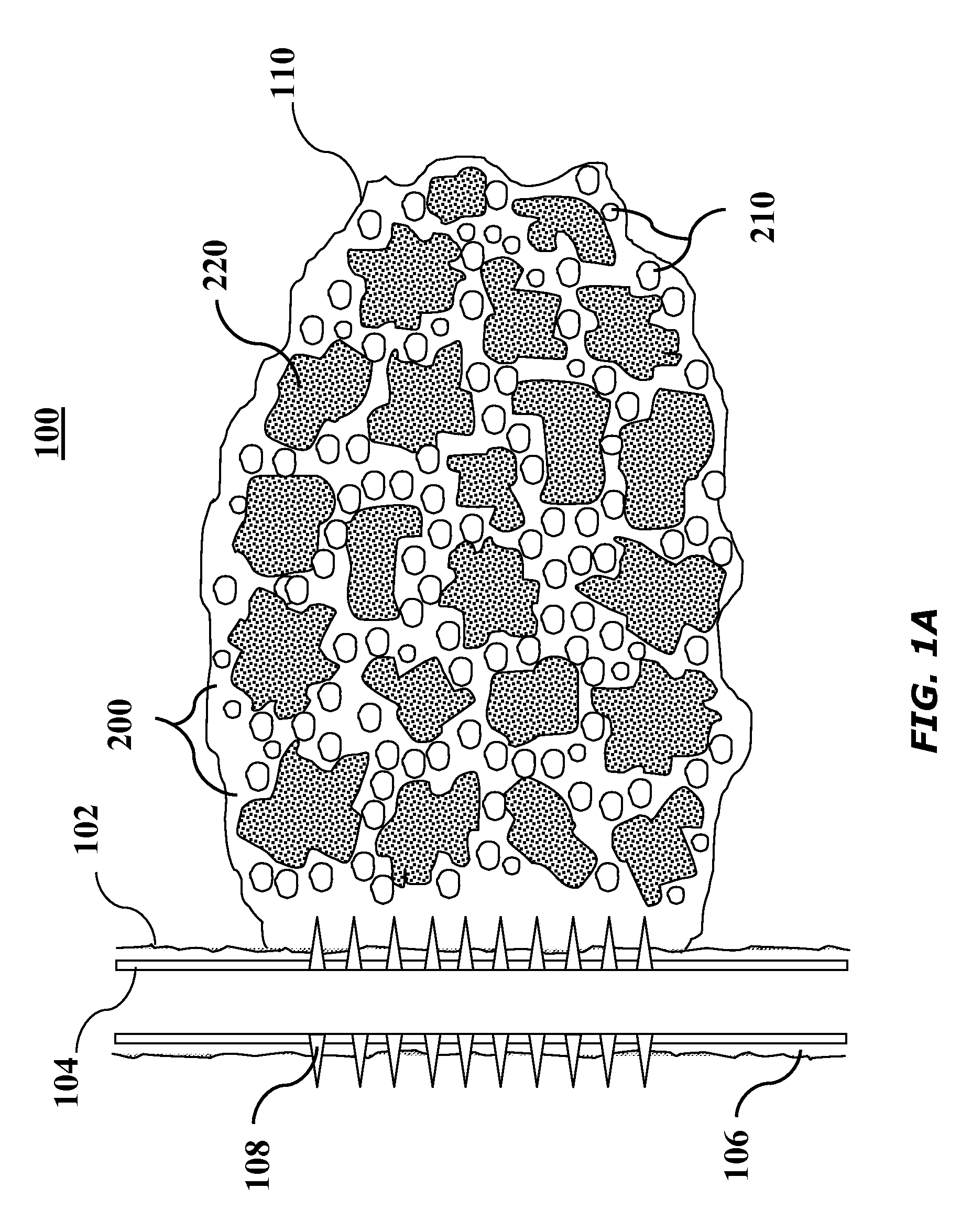
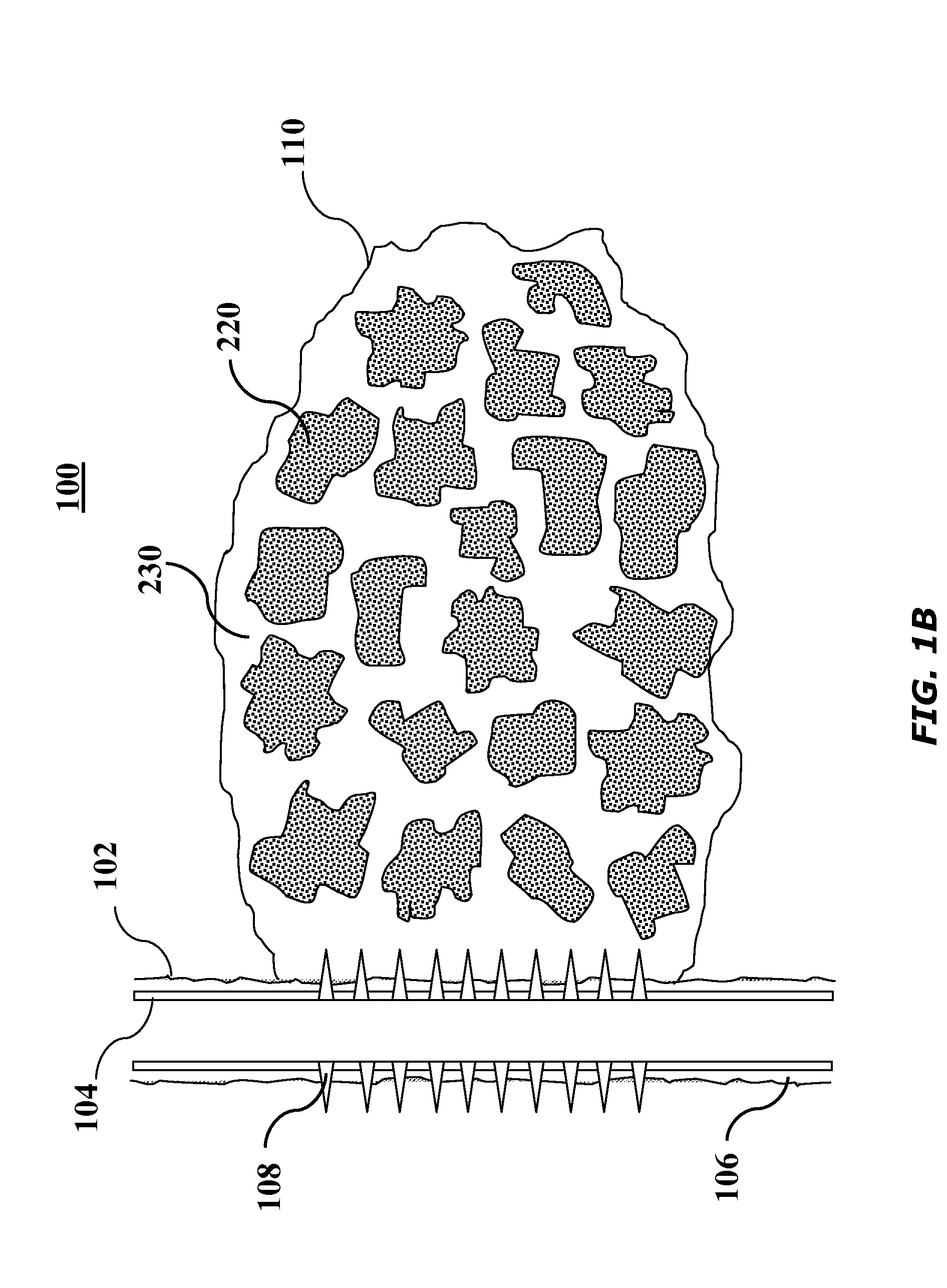
[0015]The present invention relates to high porosity propped fractures and methods of creating high porosity propped fractures in portions of subterranean formations in weakly consolidated or unconsolidated formations.

[0016]The present invention provides methods of creating high porosity fractures. In certain methods of the present invention, proppant particulates coated with a “stabilizing substance” are placed randomly within a subterranean fracture to create a high porosity propped fracture. The proppant aggregates function as pillars or masses to support and hold the fracture from completely closing. Voids or proppant-free channels surrounding the proppant aggregates greatly enhance the conductivity of the propped fracture, allowing the formation fluid to produce into or communicate with the wellbore freely. As used herein, the term “stabilizing substance” refers to a material that is capable of being coated onto a particulate and that exhibits a sticky or tacky character such t...


PUM


Abstract

Methods of fracturing a subterranean formation penetrated by a well bore, that include the steps of placing a fracturing fluid comprising a first stabilizing substance into the subterranean formation at or above a pressure sufficient to create or enhance at least one fracture in the subterranean formation; placing a treatment fluid comprising a gel carrier fluid, degradable solid-free gel bodies, and solids-laden gel bodies into the fracture such that the solids-free gel bodies and the solids-laden gel bodies form multiple packs within the fracture; and, breaking the gel carrier fluid and allowing the solid-free gel bodies to degrade to create a high porosity propped fracture formed of the solids-laden gel bodies wherein the propped fracture has a porosity of at least about 40%.

Description

BACKGROUND[0001]The present invention relates to high porosity propped fractures and methods of creating high porosity propped fractures in portions of subterranean formations in weakly consolidated or unconsolidated formations.[0002]Subterranean wells (such as hydrocarbon producing wells, water producing wells, and injection wells) are often stimulated by hydraulic fracturing treatments. In hydraulic fracturing treatments, a viscous fracturing fluid, which also functions as a carrier fluid, is pumped into a portion of a subterranean formation at a rate and pressure such that the subterranean formation breaks down and one or more fractures are formed. Typically, particulate solids, such as graded sand, are suspended in a portion of the fracturing fluid and then deposited in the fractures. These particulate solids, or “proppant particulates,” serve to prevent the fractures from fully closing once the hydraulic pressure is removed. By keeping the fracture from fully closing, the propp...

Claims


Application Information

Patent Timeline
IPC IPC(8): E21B43/26
CPCC09K2208/08C09K8/685
Inventor NGUYEN, PHILIP D.
Owner HALLIBURTON ENERGY SERVICES INC
Why Eureka
Try Eureka