Eureka AIR delivers breakthrough ideas for toughest innovation challenges, trusted by R&D personnel around the world.

Keycap and method of manufacturing the same

a technology of keycaps and manufacturing methods, applied in the field of keycaps, can solve the problems of large time consumption, achieve the effects of reducing the total manufacturing time, improving manufacturing stability, and high energy

Inactive Publication Date: 2013-09-26
DARFON ELECTRONICS CORP
View PDF13 Cites 8 Cited by
  • Summary
  • Abstract
  • Description
  • Claims
  • Application Information

AI Technical Summary

Benefits of technology

This patent describes a method for manufacturing a keycap that reduces the time required for production and improves stability. The keycap is made by a process that involves injection-molding a cap with ink, then using a laser to add a pattern to the ink. A layer of light-permeable protection is then added to cover the pattern. This method also improves the binding strength between the ink and the cap, making the keycap more reliable. Overall, this innovation provides a more efficient and stable way to produce keycaps with intricate patterns.

Problems solved by technology

Therefore, the keycap needs many processes, leading to a great consumption of time, especially of much time to form the multiple layers of ink.

Method used


Image

  • Keycap and method of manufacturing the same
  • Keycap and method of manufacturing the same
  • Keycap and method of manufacturing the same

Examples


Embodiment Construction

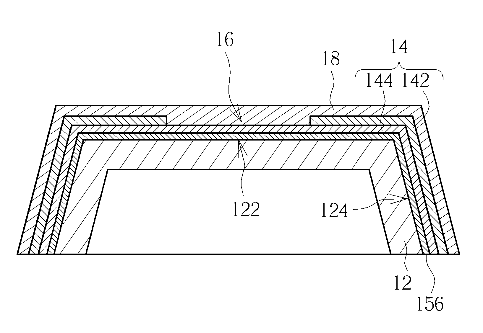
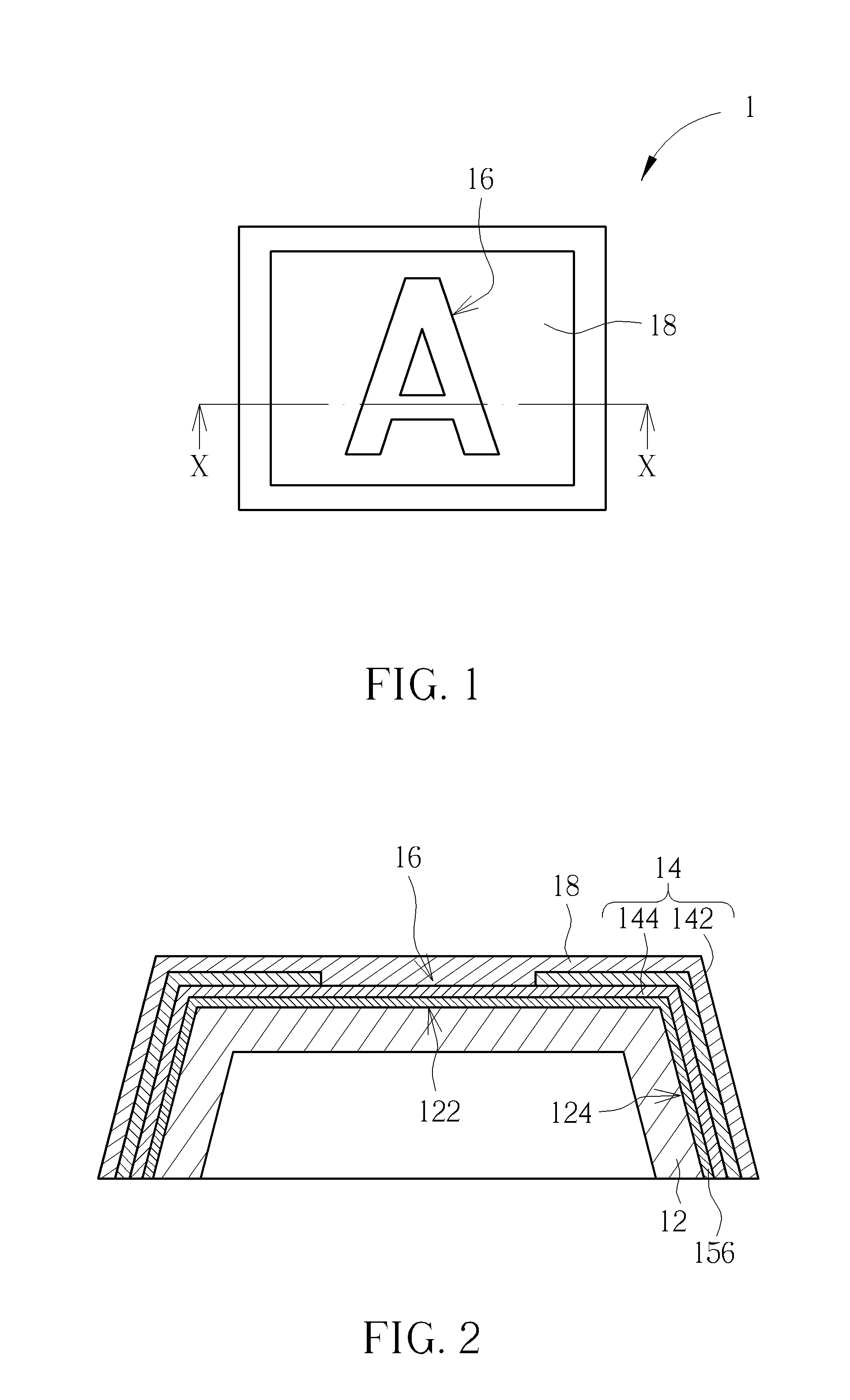
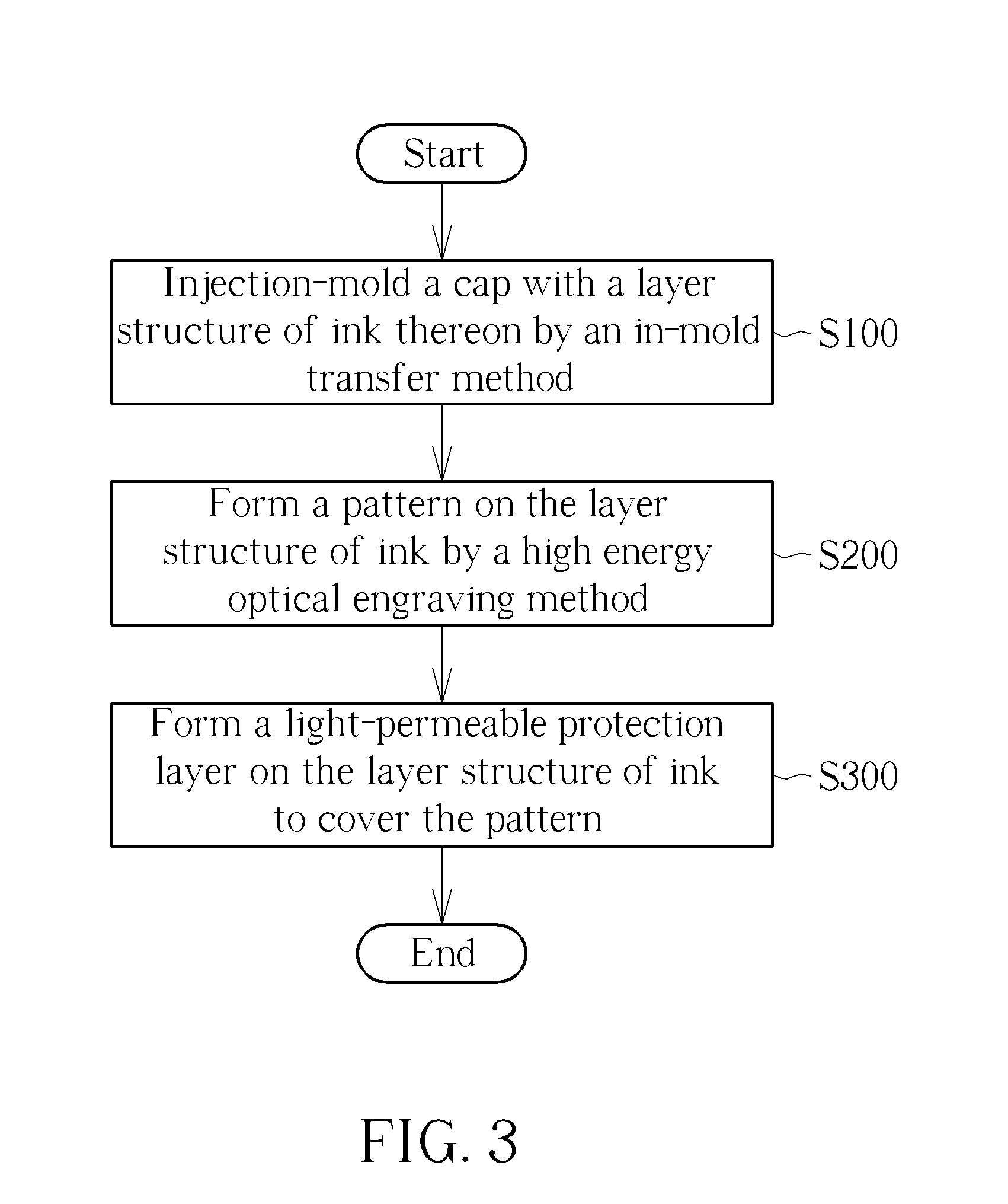
[0017]Please refer to FIGS. 1 through 3. FIG. 1 is a top view of a keycap 1 of a preferred embodiment according to the invention. FIG. 2 is a sectional view of the keycap 1 along the line X-X in FIG. 1. FIG. 3 is a primary flow chart of a method of manufacturing keycap according to the invention. As shown by the step S100, the method is first to injection-mold a cap 12 with a layer structure of ink 14 thereon by an in-mold transfer method. As shown by the step S200, the method is then to form a pattern 16 on the layer structure of ink 14 by a high energy optical engraving method. In the embodiment, the pattern 16 presents a letter A, but the invention is not limited thereto. Afterward, as shown by the step S300, the method is to form a light-permeable protection layer 18 on the layer structure of ink 14 to cover the pattern 16. Thereby, the manufacturing of the keycap 1 uses the in-mold transfer method for enhancing the efficiency of forming the layer structure of ink 14 on the cap ...


PUM

PropertyMeasurementUnit
layer structureaaaaaaaaaa
structureaaaaaaaaaa
permeableaaaaaaaaaa

Abstract

A keycap and a method of manufacturing the same are disclosed. The method is to injection-mold a cap with a layer structure of ink thereon by an in-mold transfer method; then, to form a pattern on the layer structure of ink by a high energy optical engraving method; and at last, to form a light-permeable protection layer on the layer structure of ink to cover the pattern. The keycap according to the invention is therefore obtained. Therefore, the invention can reduce the manufacturing time relatively to a conventional keycap with a pattern formed thereon, such as a keycap for backlight keyboard. Furthermore, the invention can improve the binding strength between the layer structure of ink and the cap by use of the in-mold transfer method.

Description

BACKGROUND OF THE INVENTION[0001]1. Field of the Invention[0002]The invention relates to a keycap and a method of manufacturing keycap, and especially relates to a keycap with pattern thereon and a method therefor.[0003]2. Description of the Prior Art[0004]Current keycaps are usually made by injection-molding. If it is required to form a pattern on the keycap, the pattern is usually formed in another process separate from the above injection-molding process. For an example of a keycap used in a backlight keyboard, a transparent cap is first formed by injection-molding. The cap is then printed or coated with multiple layers of ink thereon by an order. A pattern is formed by using laser light to cut (or mark) the multiple layers of ink. At last, a protection gel layer is formed on the multiple layers, especially over the pattern by spraying and is treated by a curing process. Afterward, the keycap with the pattern is therefore obtained. Therefore, the keycap needs many processes, lead...

Claims


Application Information

Patent Timeline
Patent Type & Authority Applications(United States)
IPC IPC(8): H01H9/02B29C59/16
CPCH01H9/02B29C59/16H01H13/88H01H2009/187B29C2037/0042H01H2221/07H01H2229/044B29C37/0032B29C2035/0827H01H2209/016
Inventor HU, TSAI-JUNGCHANG, YA-TING
Owner DARFON ELECTRONICS CORP
Why Eureka
Eureka Blog
Learn More