Fundus camera

a technology of ophthalmology and camera body, which is applied in the field of ophthalmological photographing equipment, can solve the problems of insufficient patient care for patients with severe ametropia, limited moving range of the focus index subassembly, and inability to continuously fine-tune the focus adjustmen

Inactive Publication Date: 2013-09-26
OPTOVUE
View PDF7 Cites 31 Cited by
  • Summary
  • Abstract
  • Description
  • Claims
  • Application Information

AI Technical Summary

Problems solved by technology

Due to engineering limitations of the system design, the total diopter range for continuous focus adjustment (by either moving the focus lens or the sensor) of a conventional fundus camera is typically less than 30 diopters and is not enough for patients with severe ametropia.
However, the moving range of the focus index subassembly is limited compared to that of the focus adjustment of the imaging path when the DC lens is used.
Therefore, continuous fine focus adjustment is not possible in the case of severe ametropia.
For the case using a non-mydriatic fundus camera to examine a severe ametropic eye, where Near Infrared (NIR) light source was used during observation, the quality of a captured color fundus image is much worse because the focus shifts between the NIR video image in the observation mode and the captured color image (still image).
However, this approach is not suitable for compact system design where space is very limited.
However, this approach requires a strong power correction lens with large diopter scale, and inadvertently increases sensitivity to component tolerances and alignment error.

Method used


Image

  • Fundus camera
  • Fundus camera
  • Fundus camera

Examples


Embodiment Construction

[0041]Embodiments of the present invention are described herein with reference to the exemplary drawings.

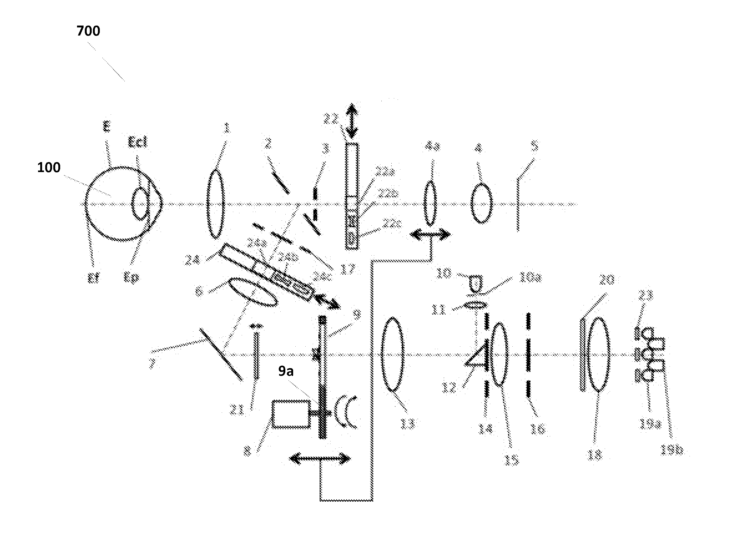
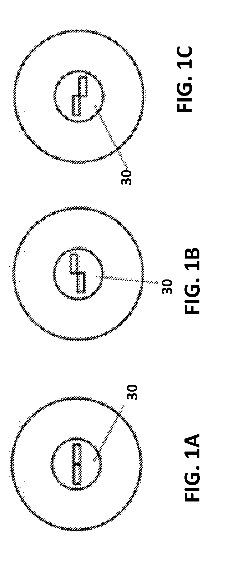
[0042]According to some embodiments of the present invention, a system and method of changing the illumination path to match the amount of diopter variation in the imaging path with a DC lens is disclosed. This allows continuous fine-focus adjustment using the focus index 30 (the split-bar) to be achieved without increase in size of the optical system. In some embodiments, a tunable lens can be used individually in either the imaging or the illumination path. Or a tunable lens can be used simultaneously in both the illumination path and the imaging path to allow continuous fine-focus adjustment.

[0043]FIG. 5A shows an exemplary schematic of a fundus camera 502 according to some embodiments where sensor 5 is movable. In FIG. 5B, a DC lens 22b is inserted into the imaging path and another DC lens 24b is also inserted into the illumination path between the cornea diaphragm 17 and the...


PUM


Abstract

An apparatus and method of providing an ophthalmic image is presented. In accordance with embodiments of the present invention, an illumination path with a focus index optical assembly and a first diopter compensator is provided and an imaging path with a sensor and a second diopter compensator is provided. The first diopter compensator and the second diopter compensator can be adjusted to provide focus according to a focus index from the focus index optical assembly.

Description

RELATED APPLICATIONS[0001]This application claims priority to U.S. Provisional Application 61 / 613,919, filed on Mar. 21, 2012, which is herein incorporated by reference in its entirety.BACKGROUND[0002]1. Field of the Invention[0003]Embodiments of the present invention are related to an ophthalmic photographing apparatus.[0004]2. Discussion of Related Art[0005]In a conventional fundus camera, a focus index, such as a split-bar pattern as, for example, shown in FIGS. 1A-1C, is usually generated from a focus index projection system using a light source with wavelength in the range of dark red to Near InfraRed (NIR) illuminating a slit. The focus index projection system is then branched into the fundus illumination path through a beam splitter or a flipping mirror (shutter) (see, for example, U.S. Pat. No. 3,925,793 A and U.S. Pat. No. 4,283,124 A). Another way of branching the focus index path into the fundus illumination path is through the projection of the focus index on to a retrac...

Claims


Application Information

Patent Timeline
Patent Type & Authority Applications(United States)
IPC IPC(8): A61B3/14A61B3/15
CPCA61B3/156A61B3/14A61B3/12
Inventor CHENG, YEOU-YENWEI, JAY
Owner OPTOVUE
Why Eureka
Try Eureka