Electronic control apparatus
a control apparatus and electronic technology, applied in the direction of cooling/ventilation/heating modification, semiconductor devices, casings with connectors, etc., can solve the problem of insufficient radiation of heat from the outer wall surface of the housing member into the atmospher
- Summary
- Abstract
- Description
- Claims
- Application Information
AI Technical Summary
Benefits of technology
Problems solved by technology
Method used
Image

Examples
first example
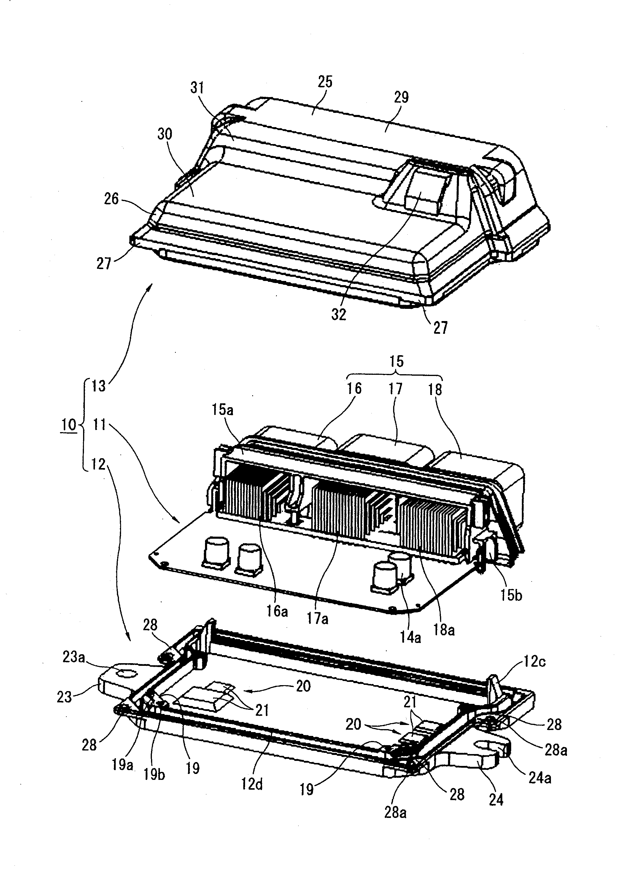
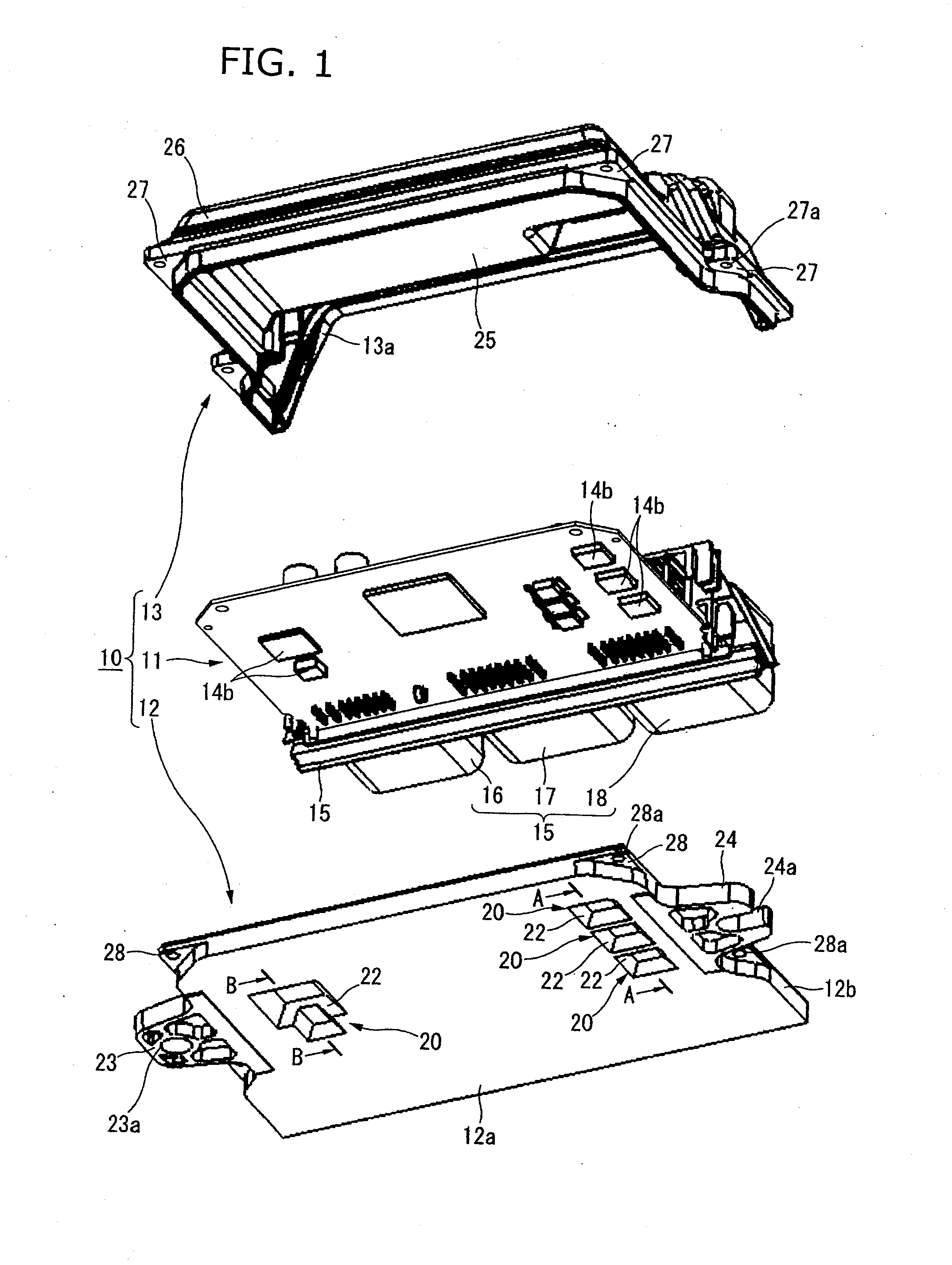
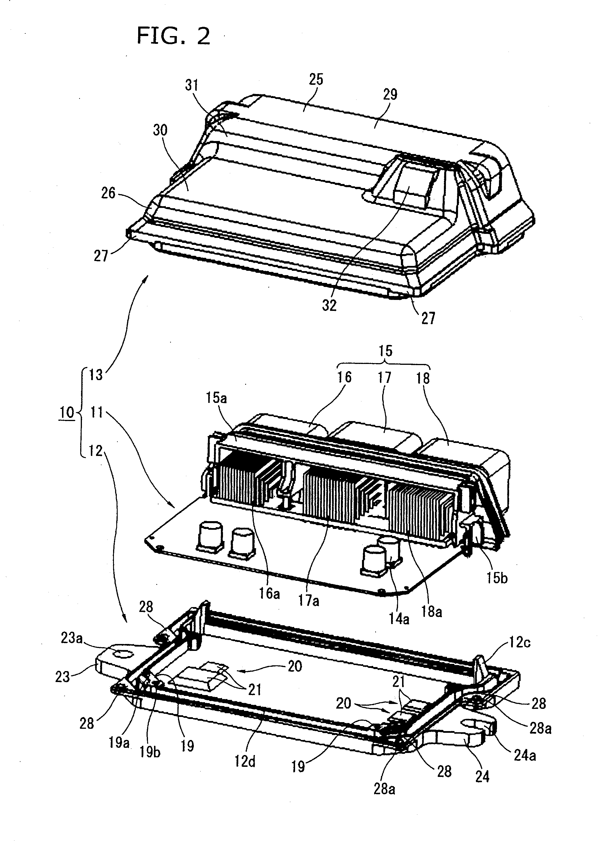
[0029]In a first example, the heat radiating portion 20 formed by one convex portion 21 and one concave portion 22 is provided for one of the respective heat-generating electronic components 14b mounted in the lower side (i.e., on the case-side surface) of the circuit board 11. As shown in FIG. 3, each heat radiating portion 20 is formed at a location opposed to (i.e., a location facing) the heat-generating electronic component 14b mounted on the lower surface of the circuit board 11. Each heat radiating portion 20 is close to the heat-generating electronic component 14b through the clearance (distance “a” of FIG. 3). Each convex portion 21 includes a flat closest surface 21a at a tip side of the convex portion 21 which constitutes an upper portion (i.e., an inner portion) of the heat radiating portion 20. The flat closest surface 21a is formed in a shape similar to a lower surface (i.e., a case-side surface) of the heat-generating electronic component 14b. As mentioned above, the c...
second example
[0031]In a second example according to the present invention, a heat radiating portion 20 formed by a plurality of convex portions 21 is provided for a plurality of heat-generating electronic components 14b which are mounted adjacent to each other on the lower surface of the circuit board 11. As shown in FIG. 4, the heat radiating portion 20 including the plurality of convex portions 21 is formed at a location opposed to (i.e., a location facing) two heat-generating electronic components 14b which are adjacent to each other and have shapes different from each other. The two convex portions 21 of the heat radiating portion 20 are respectively close to the two heat-generating electronic components 14b through the clearances therebetween. In the case of FIG. 4, the heat-generating electronic components 14b have thicknesses different from each other, with respect to the up-down direction of the drawings (i.e., with respect to the thickness direction of the circuit board 11). Hence, the ...
third example
[0033]In a third example according to the present invention, the heat-generating electronic component 14b is mounted on the upper surface (i.e., the cover-side surface) of the circuit board 11. The heat radiating portion 20 is formed for a heat-generating region 14c which is a lower portion (i.e., a case-side portion) of the circuit board 11 and which is located directly below the heat-generating electronic component 14b. That is, the heat-generating region 14c is located at a lower side (opposite-surface side) of the circuit board 11 over an existing range of the heat-generating electronic component 14b mounted on the upper surface of the circuit board 11. As shown in FIG. 5, the heat radiating portion 20 is formed at a location opposed to (i.e., a location facing) the heat-generating region 14c. The heat radiating portion 20 is close to the heat-generating region 14c through a clearance. Each convex portion 21 includes the flat closest surface 21a at the tip of the convex portion ...
PUM
 Abstract
Description
Claims
Application Information
 - R&D
- Intellectual Property
- Life Sciences
- Materials
- Tech Scout
- Unparalleled Data Quality
- Higher Quality Content
- 60% Fewer Hallucinations
Browse by: Latest US Patents, China's latest patents, Technical Efficacy Thesaurus, Application Domain, Technology Topic, Popular Technical Reports.
© 2025 PatSnap. All rights reserved.Legal|Privacy policy|Modern Slavery Act Transparency Statement|Sitemap|About US| Contact US: help@patsnap.com