
Chip card holding mechanism and electronic device using the same

a technology of holding mechanism and chip card, which is applied in the direction of card stiffeners, instruments, conveying record carriers, etc., can solve the problems of inconvenient removal and replacement of chip cards, chip card holding mechanisms may not unlock, and complex structures of holding mechanisms

Inactive Publication Date: 2013-09-26
FU TAI HUA IND SHENZHEN +1
View PDF1 Cites 14 Cited by
  • Summary
  • Abstract
  • Description
  • Claims
  • Application Information

AI Technical Summary

Benefits of technology

The patent is for a mechanism used in a small electronic device that holds a chip card. The mechanism includes a locking mechanism that can be unlocked using a special tool. The technical benefit is that this mechanism allows for easy and secure access to the chip card in the electronic device, making it easier to develop and test new technology.

Problems solved by technology

When detaching or replacing the chip card, a user must detach the outer cover from the portable electronic device first, thereby exposing the chip card holding mechanism; thus, removal and replacement of the chip card is inconvenient.
In addition, conventional chip card holding mechanisms have complex structures, and the chip card holding mechanisms may not unlock if the pressure exerted from the pushing done by the user is not sufficient enough to rotate the holding member.
On the other hand, excess pressure exerted from the pushing may cause damage to the holding mechanism.

Method used


Image

  • Chip card holding mechanism and electronic device using the same
  • Chip card holding mechanism and electronic device using the same
  • Chip card holding mechanism and electronic device using the same

Examples


Embodiment Construction

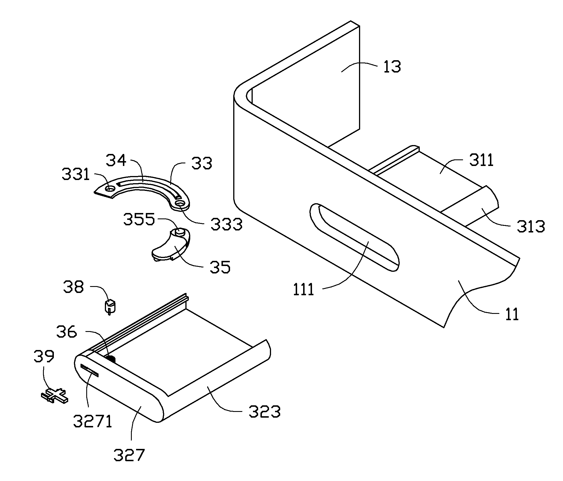
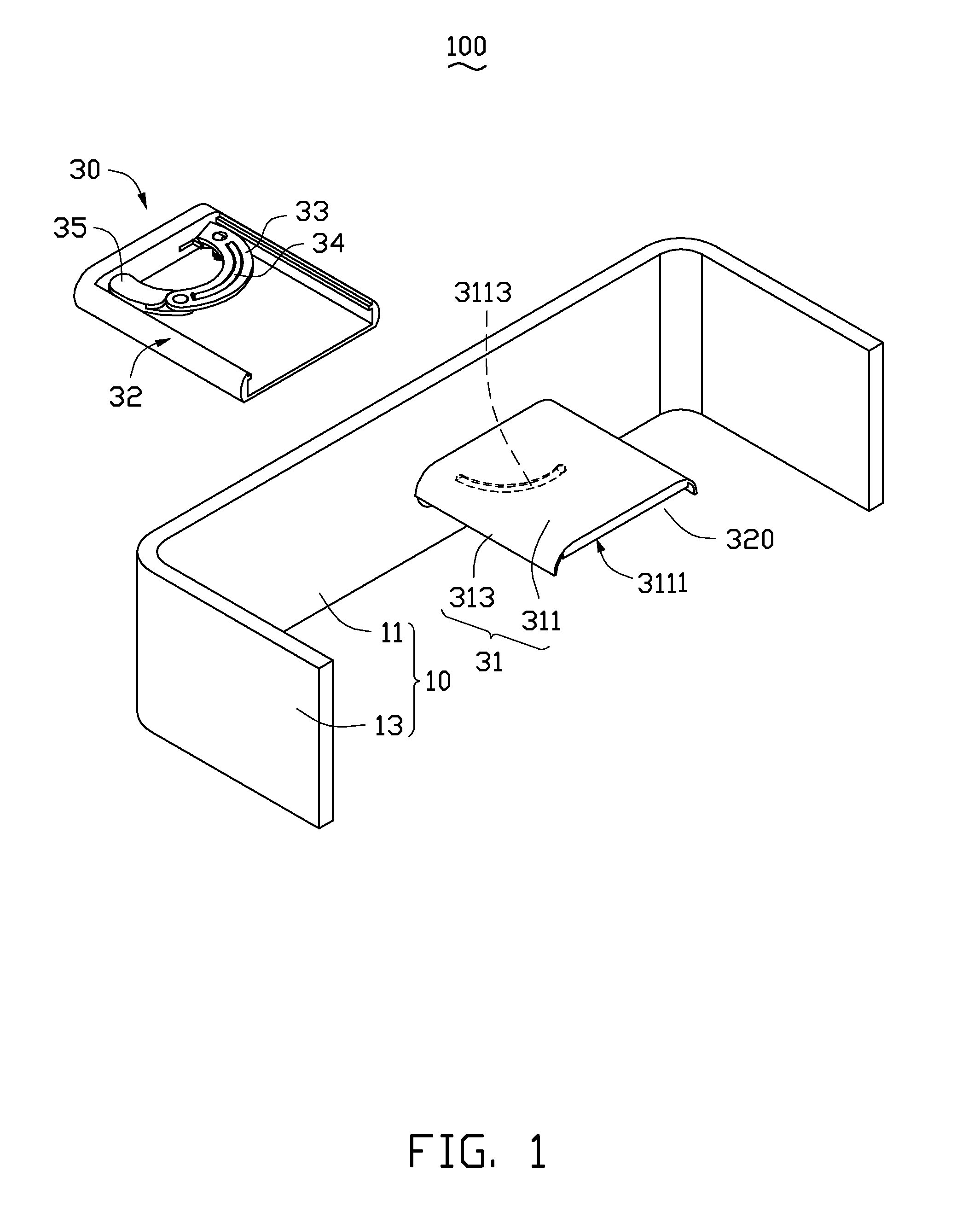
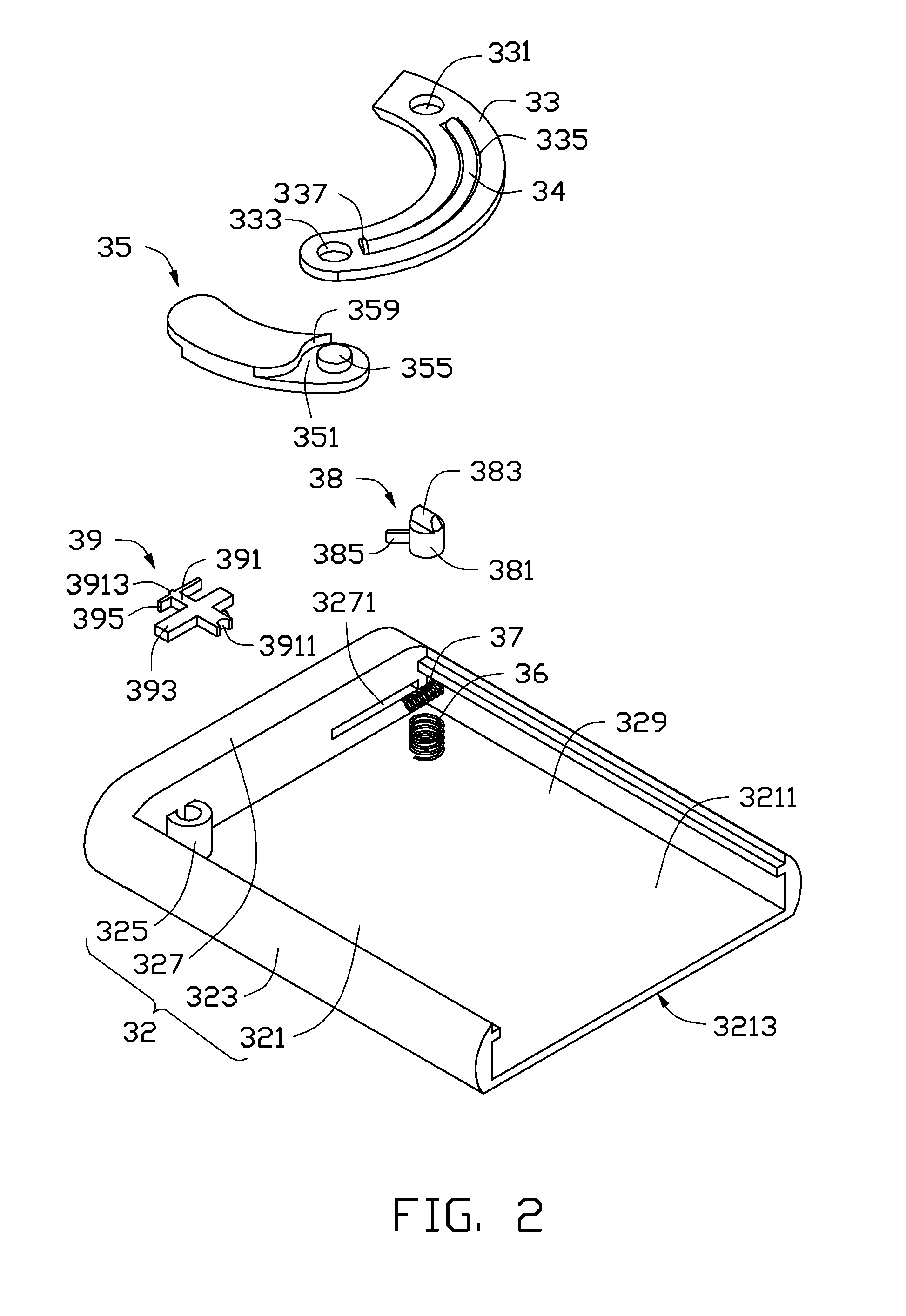
[0016]FIGS. 1 and 2 show an embodiment of an electronic device 100 including a partial view of a housing 10, and a chip card holding mechanism 30 engaged with the housing 10. The chip card holding mechanism 30 is configured to hold / secure a chip card within the electronic device 100. The electronic device 100 may be a portable electronic device. In the illustrated embodiment, the chip card holding mechanism 30 is configured to receive and hold a SIM card (not shown), for connecting the SIM card with a connector (not shown) of the electronic device 100, thereby enabling the SIM card to achieve or perform its function. In other embodiments, the chip card holding mechanism 30 may be used to hold other kinds of chip cards, such as SD cards or CF cards, for example.

[0017]FIG. 3 shows a partial view of the housing 10 including a first sidewall 11 and a pair of second sidewalls 13 perpendicularly extending from the first sidewall 11 parallel to each other. The first sidewall 11 is located ...


PUM


Abstract

A chip card holding mechanism includes a tray, a supporting plate, an unlocking member, a driving arm, and an elastic member. The unlocking member includes a base body, an unlocking block formed on the base body, and a rotation portion protruding from the base body. The supporting plate defines a first sliding groove, and forms a first block. The driving arm defines a second sliding groove, and forms a second block positioned thereon. The first block is received in the second sliding groove, and the second block is received in the first sliding groove. The elastic member is compressed between the first block and the second block. The rotation of the rotation portion is capable of driving the unlocking block to rotate, thereby releasing the elastic member.

Description

BACKGROUND[0001]1. Technical Field[0002]The present disclosure relates to holding mechanisms, and particularly to a chip card holding mechanism and an electronic device using the same.[0003]2. Description of Related Art[0004]Portable electronic devices such as mobile phones and tablet computers may employ at least one chip card (e.g., SIM card) for storing information, connecting to the internet, dialing calls, and the like. It is necessary to provide a chip card holding mechanism for holding / securing the chip card within the portable electronic device. The chip card holding mechanism may define a receiving space, an elastic sheet fitted in the receiving space, and a holding member rotatably assembled on the housing of the portable electronic device. The chip card can be received and held in the receiving space by the holding member, with the chip card resisting the elastic sheet. When detaching or replacing the chip card, a user must detach the outer cover from the portable electro...

Claims


Application Information

Patent Timeline
Patent Type & Authority Applications(United States)
IPC IPC(8): H05K7/14
CPCH05K7/1461G06K13/085H05K7/1402
Inventor WANG, HUA-YONG
Owner FU TAI HUA IND SHENZHEN
Learn More