
Medical Image Quality Monitoring and Improvement System

a medical image and quality improvement technology, applied in the field of medical image quality reporting and monitoring system, can solve the problems of unsatisfactory imaging system users, inability to achieve the desired level of image quality, and insufficient investigation of such complaints, so as to achieve the effect of reducing quality, reducing quality, and expressing dissatisfaction

Active Publication Date: 2013-09-26
SIEMENS HEALTHCARE GMBH
View PDF14 Cites 16 Cited by
  • Summary
  • Abstract
  • Description
  • Claims
  • Application Information

AI Technical Summary

Benefits of technology

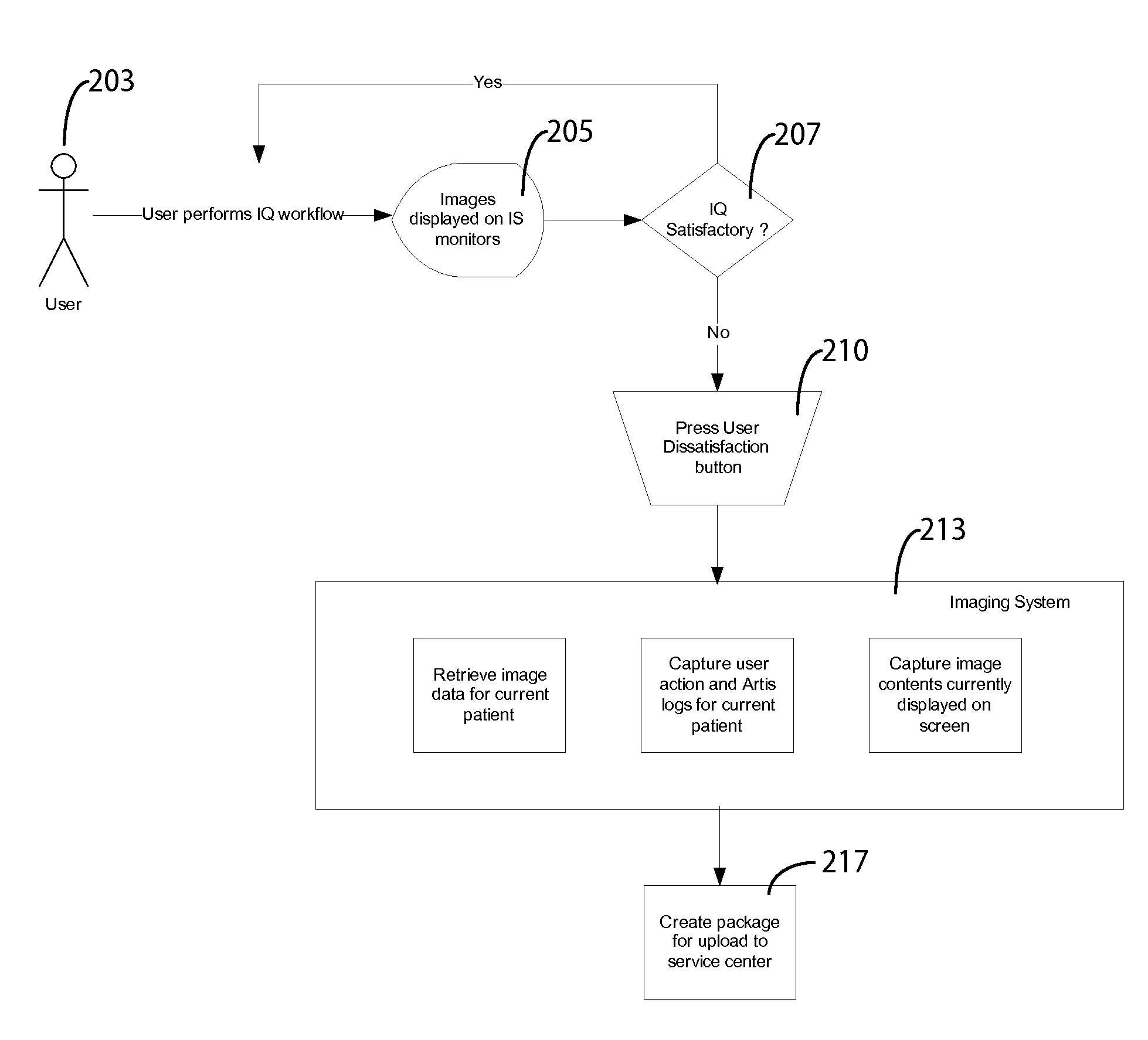
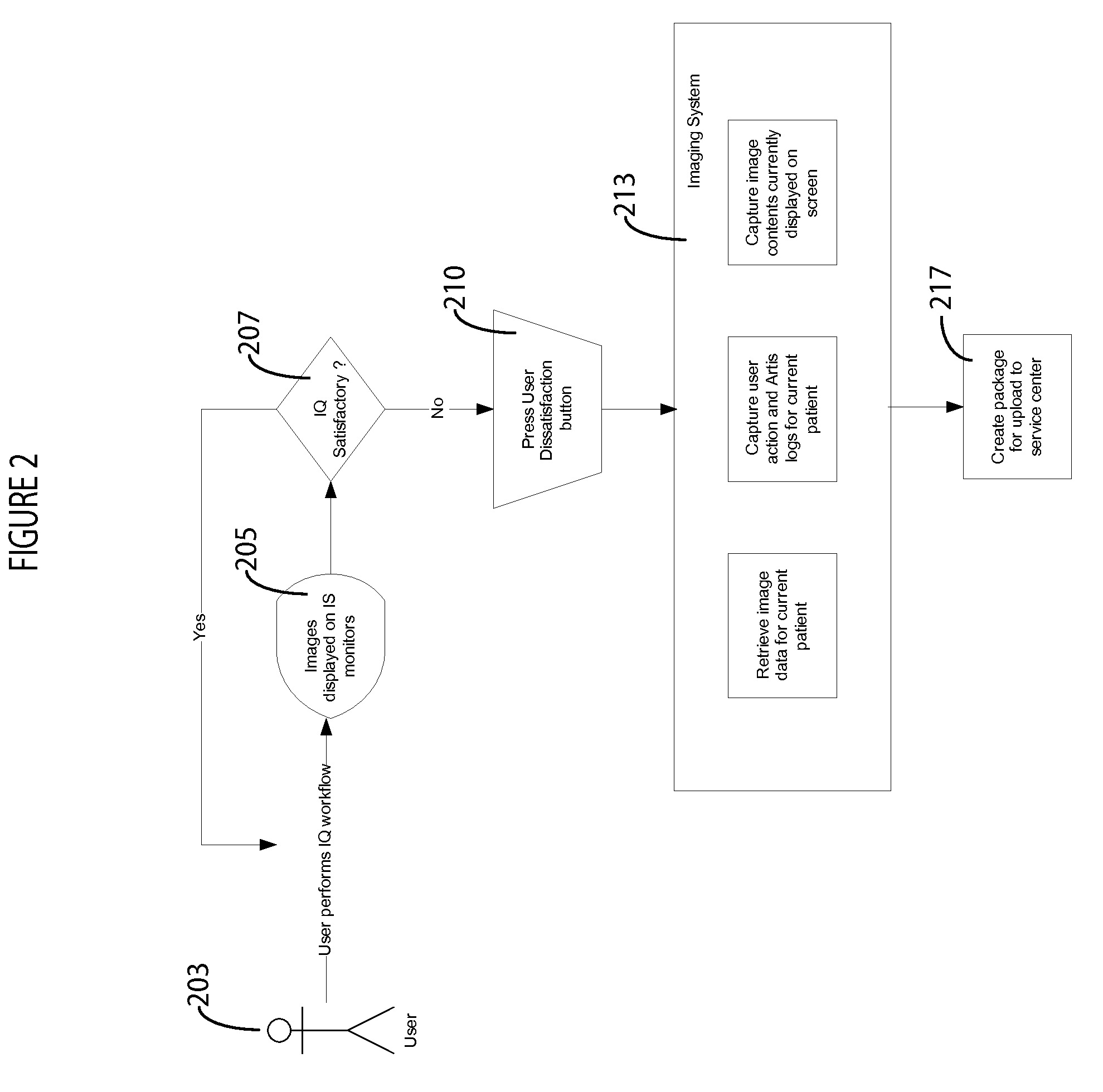
The patent text describes a system that allows medical professionals to express their dissatisfaction with the quality of medical images through a simple button press on a computer. In response, the system automatically gathers relevant information to investigate and examine the image quality. This system could help improve image quality and provide a more efficient way of managing medical images in a healthcare setting.

Problems solved by technology

In response to a user performing image acquisition and review using an angiography imaging system, a desired level of image quality may not be attained due to a variety of reasons such as incorrect use of image processing settings and sub-optimal performance of image processing methods or other software defects.
Often such occurrences are sporadic or associated with a particular workflow performed by a particular user and expressed as a complaint and dissatisfaction to service personnel or image quality experts.
Further investigation of such complaints takes substantial effort and resources (involving multiple visits to a reporting site to acquire data such as acquired image, image examination data sets, data indicating performed workflow and engineering logs, for example).
A complaint may also be overlooked and may not get investigated due to a non-reproducible nature of a problem, leaving an imaging system user dissatisfied.

Method used


Image

  • Medical Image Quality Monitoring and Improvement System
  • Medical Image Quality Monitoring and Improvement System
  • Medical Image Quality Monitoring and Improvement System

Examples


Embodiment Construction

[0010]A system enables a user to express dissatisfaction with quality of an image acquisition outcome via simple button press on a patient table side user interface (UI), computer workstation or other displayed image and in response acquires relevant information for investigation and examination assessment without manual intervention of service personnel or image quality experts. In response to observing unsatisfactory image quality at the end of, or during, an image processing workflow using an angiography system, for example, a user is able to report an image quality problem via pressing a special button provided on a table side control, or other user interface display image on a workstation.

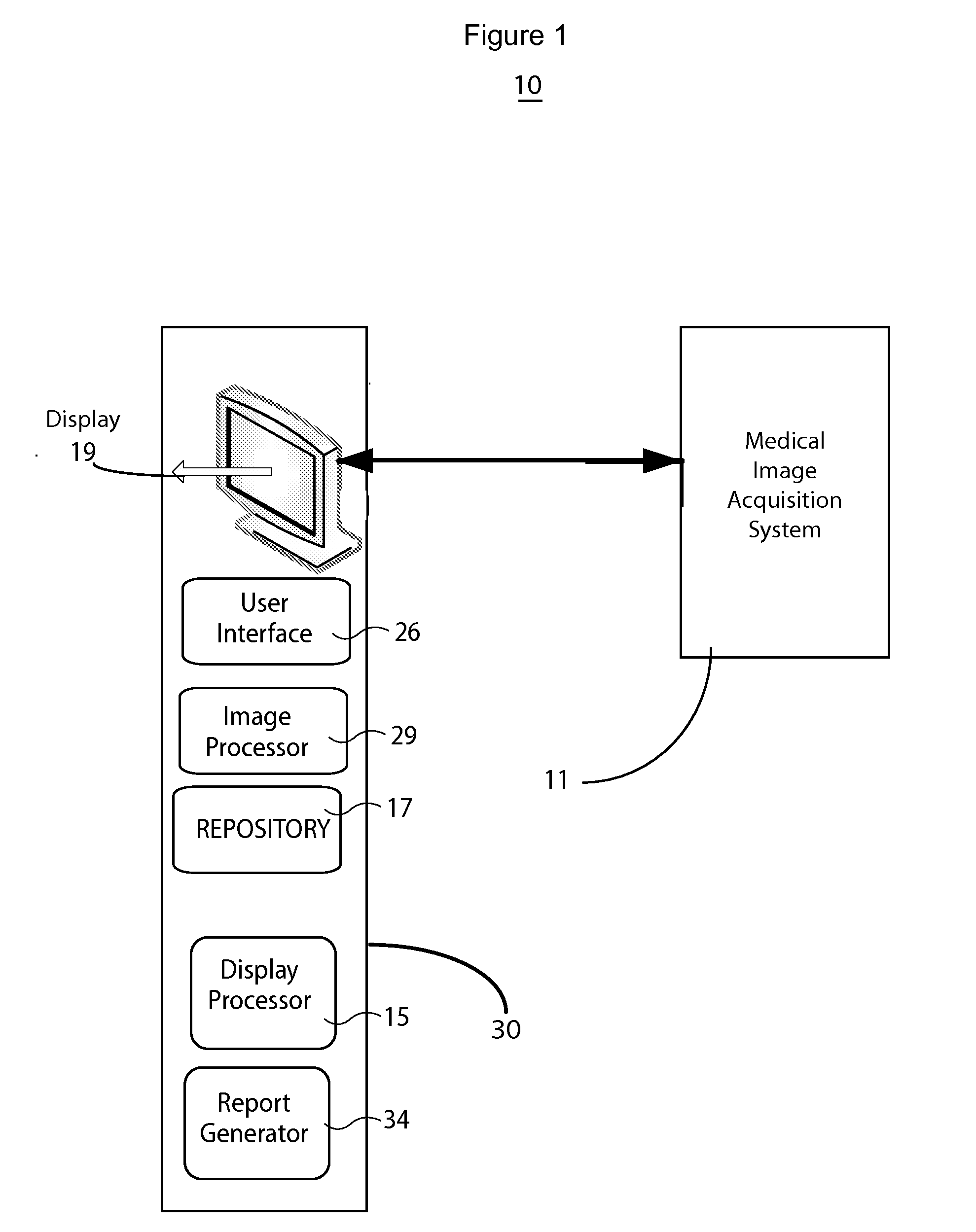
[0011]FIG. 1 shows medical image quality reporting and monitoring system 10 for use in a medical imaging system. System 10 comprises image acquisition device 11 bidirectionally communicating with at least one medical image computer system, workstation, server or other processing device 30 incl...


PUM


Abstract

A medical image quality reporting and monitoring system for use in a medical imaging system comprises a medical image computer including, a display processor, a display and a report generator. The display processor generates data representing an image for display including a user selectable image element enabling a user to identify at least one medical image as having an image quality deficiency. The display presents the image. The report generator, in response to detection of selection of the image element, identifying at least one medical reduced quality image as having an image quality deficiency, automatically generates a report. The report comprises, data representing an anonymized reduced quality image having the image quality deficiency, a time of acquisition of the reduced quality image and imaging system acquisition settings used in acquiring the reduced quality image.

Description

[0001]This is a non-provisional application of provisional application Ser. No. 61 / 613,001 filed Mar. 20, 2012, by D. Mehta.FIELD OF THE INVENTION[0002]This invention concerns a medical image quality reporting and monitoring system for automatically generating a report comprising, an anonymized reduced quality image having an image quality deficiency, a time of acquisition of the image and imaging system acquisition settings used in acquiring the image, in response to a determined image quality deficiency.BACKGROUND OF THE INVENTION[0003]In response to a user performing image acquisition and review using an angiography imaging system, a desired level of image quality may not be attained due to a variety of reasons such as incorrect use of image processing settings and sub-optimal performance of image processing methods or other software defects. Often such occurrences are sporadic or associated with a particular workflow performed by a particular user and expressed as a complaint an...

Claims


Application Information

Patent Timeline
Patent Type & Authority Applications(United States)
IPC IPC(8): G06T7/00
CPCG06F19/321G06T7/0012G16H30/40
Inventor MEHTA, DARSHAN
Owner SIEMENS HEALTHCARE GMBH
Learn More