Electronic pipette

a technology of electronic pipette and pipette body, which is applied in the field of electronic pipette, can solve the problems of inability to execute the basic function of the pipette without the operating and/or displayed modules, and cannot be displayed, so as to reduce the equipping of the device module, increase the number of units, and increase the economic effect of production

Inactive Publication Date: 2013-10-03
EPPENDORF AG
View PDF21 Cites 9 Cited by
  • Summary
  • Abstract
  • Description
  • Claims
  • Application Information

AI Technical Summary

Benefits of technology

[0034]According to one embodiment, the laboratory device has operating units for starting, controlling and ending workflows, and at least one display unit. In addition, at least some of the operating and / or display units are arranged on the device module, and at least some of the operating and / or display units are arranged on the operating and / or display module. This decreases the equipping of the device module with operating and / or display units. According to one embodiment, the operating and / or display module—in addition to the other operating and / or display units—has additional operating and / or display units that the device module also has. This optionally allows certain operations to be performed with the operating and / or display module or the device module, or for displays to be read by the user from the operating and / or display module or the device module. According to another embodiment, the laboratory device has operating units for adjusting and / or programming workflows, and these operating units are assigned to the device module and operating and / or display module corresponding to the operating units for starting, controlling and ending workflows. According to one embodiment, the device module only has operating units for starting and / or controlling and / or ending workflows, and the operating and / or display module has the other operating units. According to another embodiment, the display units are exclusively arranged on the operating and / or display module.
[0035]The operating and / or display unit enables savings since it can be designed to be useable for a plurality of device modules of the same kind and / or for device modules that are different. This consequently enables a plurality of equivalent or respectively different device modules to manage with a single operating and / or display module. In addition, the manufacturer achieves a higher number of units with one specific operating and / or display module which enables more economic production. The display unit can in particular display operating data and / or performance data from the pipette. A plurality of device modules can be operated sequentially with the same operating and / or display module. It is also possible however to operate a plurality of device modules simultaneously using the same operating and / or display module. To this end, the means for wireless communication can comprise a plurality of channels, and to each device module is assigned a channel. Communication via a single channel is also possible, and the device modules can for example be assigned by means of device-specific data packets. Furthermore, one device module can work together with a plurality of operating and / or display modules, for example to operate the device module from several locations, and / or to display information about the work of the device module at several locations.

Problems solved by technology

If the device module only has a reduced operating and / or display function, it is incapable of executing the basic function of the pipette without the operating and / or displayed module, and / or displaying the operating data necessary to execute the basic function.
This relates in particular to data from the laboratory device that otherwise cannot be displayed due to lack of space.

Method used


Image

  • Electronic pipette
  • Electronic pipette
  • Electronic pipette

Examples


Embodiment Construction

[0082]While this invention may be embodied in many different forms, there are described in detail herein a specific preferred embodiment of the invention. This description is an exemplification of the principles of the invention and is not intended to limit the invention to the particular embodiment illustrated.

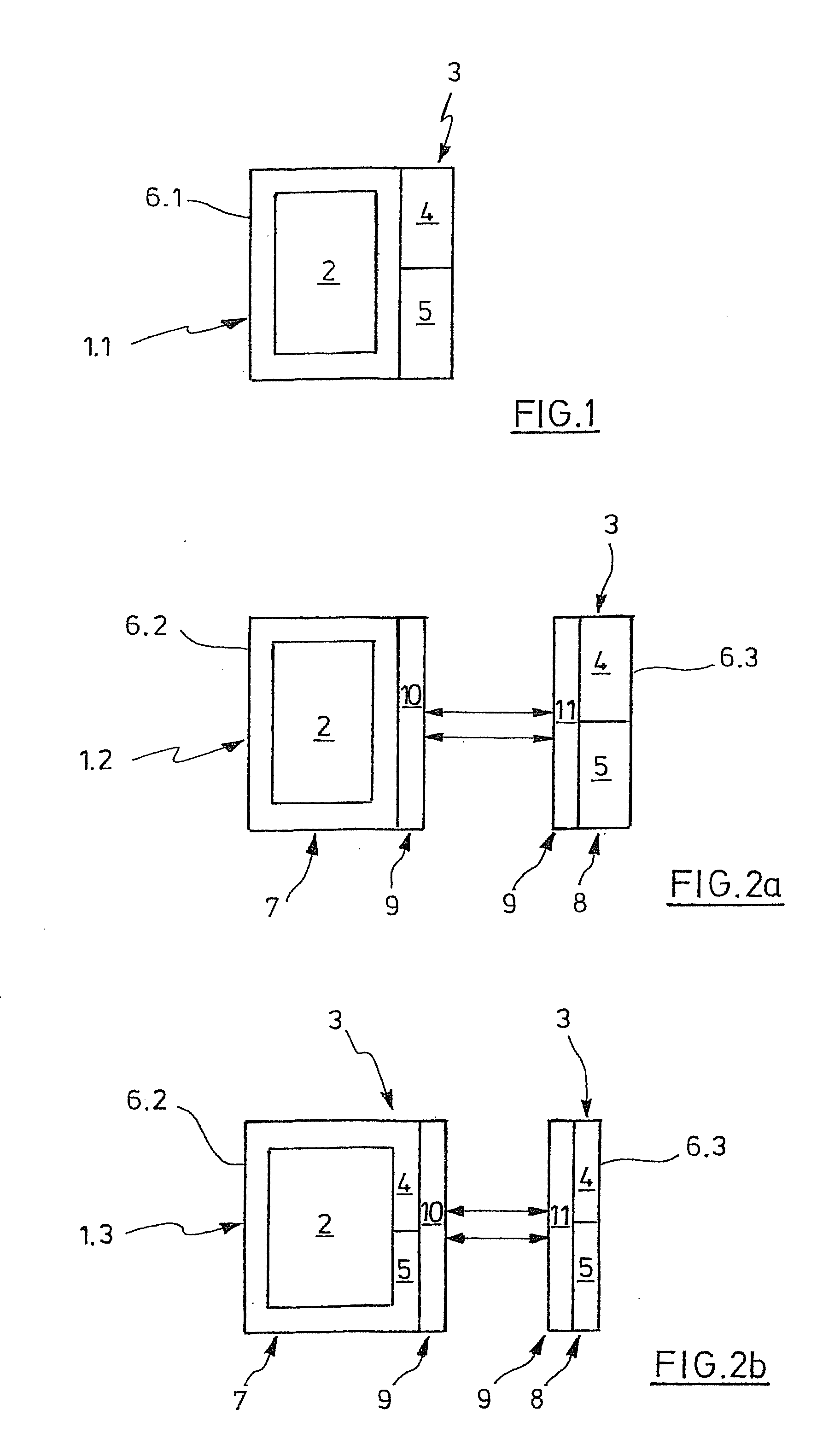
[0083]According to FIG. 1, a conventional pipette 1.1 has a unit for pipetting liquids 2 and an operating and / or display unit 3. The operating and / or display unit 3 comprises an operating unit 4 and a display unit 5. The unit for pipetting liquids 2 and the operating and / or display unit 3 are physically combined in a common housing 6.1.

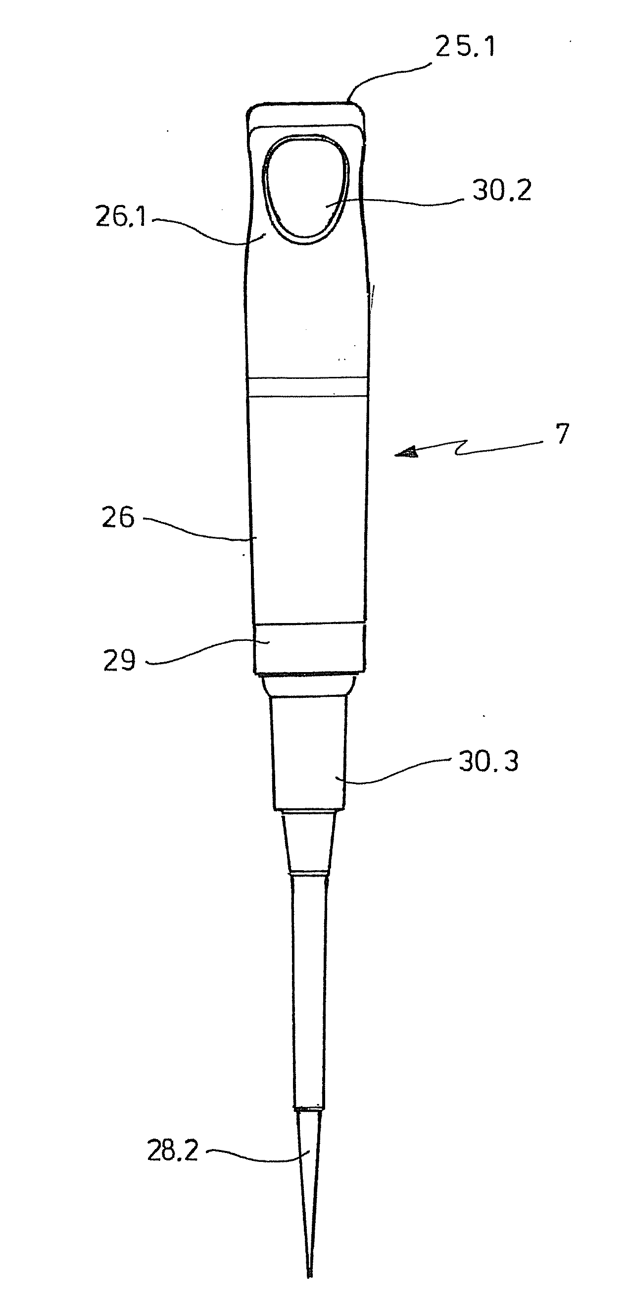
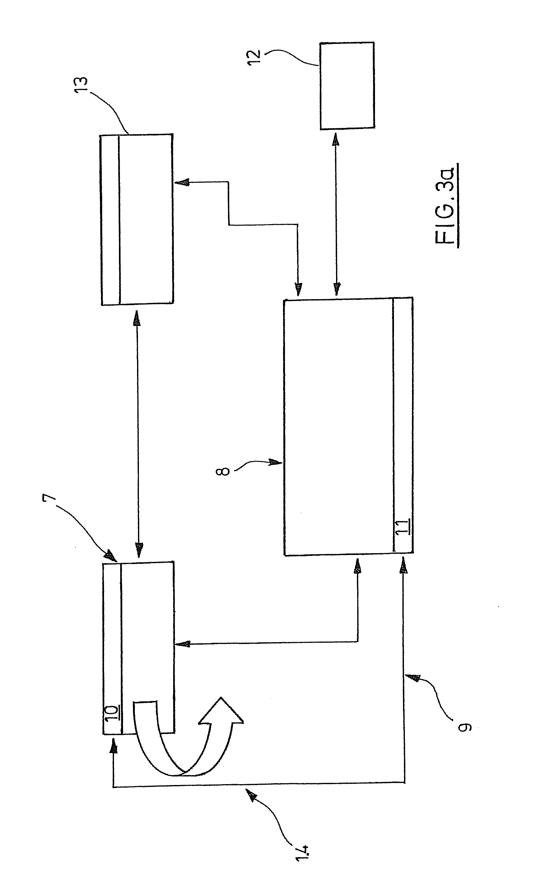
[0084]With a pipette according to the invention 1.2 according to FIG. 2a, the unit for pipetting 2 and the operating unit 4 are part of a device module 7 having a compact housing 6.2. The operating and / or display unit 5 is accommodated in a housing 6.3 of a display module 8 completely physically separate from the device module 7. The operating ...


PUM


Abstract

The invention relates to an electronic pipette comprising an electrically driven unit for pipetting and an operating and/or display unit, wherein a device module comprises a unit for pipetting, an operating and/or display module physically separate from the device module completely or partially comprises the operating and/or display unit, and means are provided for wirelessly communicating between the device module and the operating and/or display module.

Description

CROSS-REFERENCE TO RELATED APPLICATIONS[0001]This application is a national stage application of PCT / EP2011 / 004895, filed Sep. 30, 2011, which claims priority to provisional U.S. Patent Application No. 61 / 483,585 dated May 6, 2011, and DE 10 2010 047 826.1 filed Oct. 4, 2010, the entire contents of each of which are incorporated by reference.STATEMENT REGARDING FEDERALLY SPONSORED RESEARCH[0002]Not applicableBACKGROUND OF THE INVENTION[0003]The invention relates to an electronic pipette. Pipettes are handheld or stationary dosing devices that in particular are used in the laboratory for dosing liquids. “Liquids” mean liquid media in the form of samples that are single-phase liquids or liquid mixtures, or multiphase liquid mixtures (such as emulsions) or liquid-solid mixtures (such as suspensions) or liquid-gas mixtures (such as foams).[0004]Air displacement pipettes have a seat for releasably holding a pipette tip. A displacement unit for air is integrated in the pipette and, commun...

Claims


Application Information

Patent Timeline
Patent Type & Authority Applications(United States)
IPC IPC(8): B01L3/02
CPCB01L3/0217B01L3/0237B01L3/0279B01L3/021B01L2200/087B01L2300/023B01L2300/025B01L3/0286
Inventor MOHR, GUNTHER A.VON BEICHMANN, BORISLURZ, WERNER
Owner EPPENDORF AG
Why Eureka
Try Eureka