Oil Mist Filter

Inactive Publication Date: 2013-10-03
SUN WEI
View PDF29 Cites 18 Cited by
  • Summary
  • Abstract
  • Description
  • Claims
  • Application Information

AI Technical Summary

Benefits of technology

The present invention is an oil mist filter that improves oil filtering effectiveness by directing the flow of oil mist within its inner filtering space. This results in more effective filtration.

Problems solved by technology

First, the first filtering member 14 is provided with a slanting screen 141 located toward the inlet 114, and the slanting direction of the screen 141 will guide the oil mist to flow downward, so that the first filtering member 14 cannot be effectively used, and only the oil mist in the lower side of the space can be filtered, resulting in low filtering efficiency and increase of filtering cost.
Third, the second filtering member 15 will be clogged if it is not timely replaced, and the oil mist won't be able to flow into the next filtering cylinder 12, leading to low filtering efficiency.

Method used


Image

  • Oil Mist Filter
  • Oil Mist Filter
  • Oil Mist Filter

Examples


Embodiment Construction

[0017]The present invention will be clearer from the following description when viewed together with the accompanying drawings, which show, for purpose of illustrations only, the preferred embodiment in accordance with the present invention.

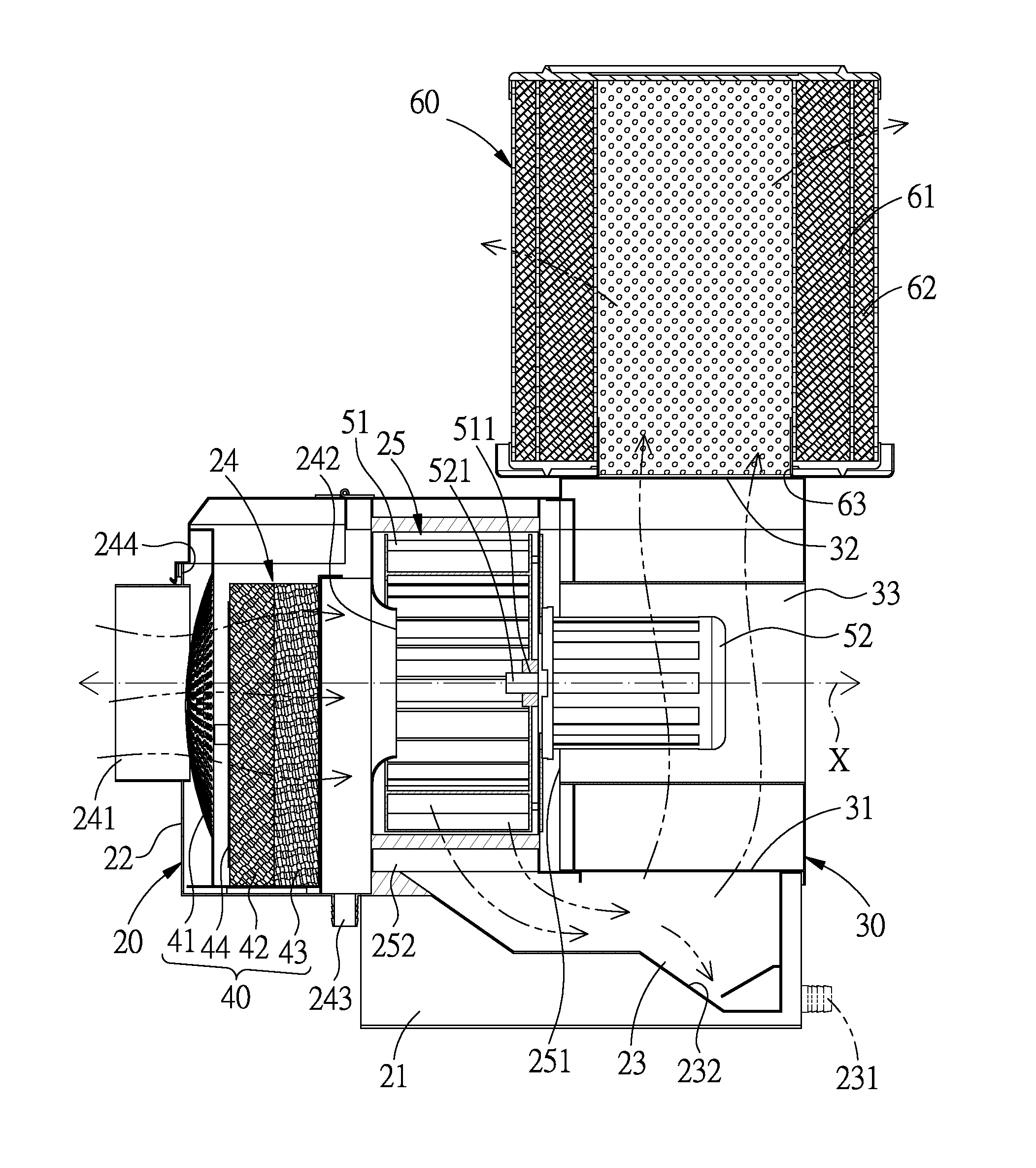
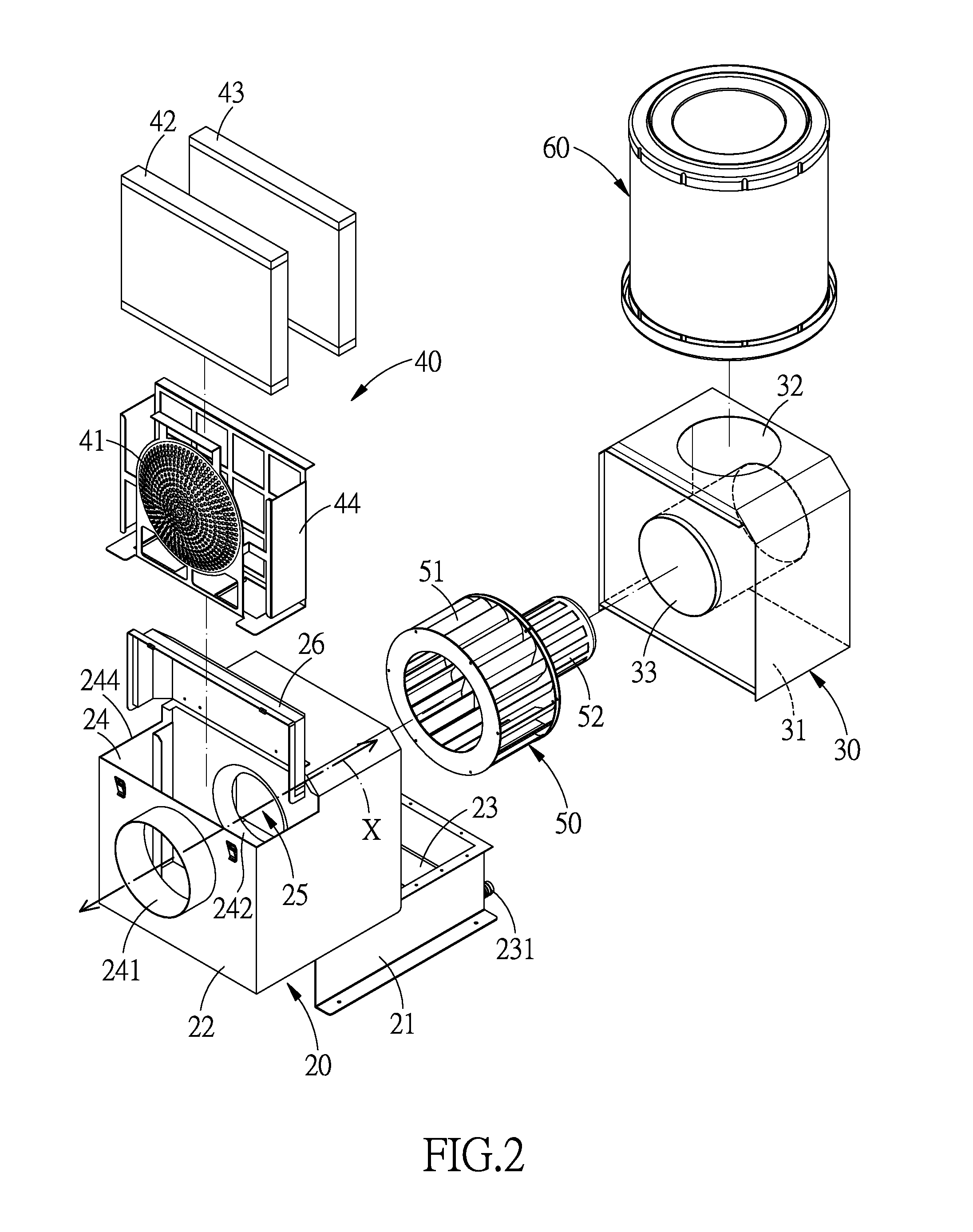
[0018]Referring to FIGS. 2-4, an oil mist filter in accordance with a preferred embodiment of the present invention comprises: a housing 20, a shell 30, a filtering assembly 40 and a sucking mechanism 50 which are disposed in the housing 20 and the shell 30, and a filtering cylinder 60 mounted outside the shell 30.

[0019]The housing 20 includes a base 21 and a top cover 22 on the base 21 which are arranged in a staggered manner. The base 21 is formed with an oil-collecting chamber 23. The top cover 22 is formed with a filtering space 24 and a sucking space 25. The housing 20 defines an axis X extending through the filtering space 24 and the sucking space 25. The filtering space 24 is formed with an intake port 241 in communication with outside, an...


PUM


Abstract

An oil mist filter is provided with a housing, a shell, a filtering assembly and a sucking mechanism which are disposed in the housing and the cover, and a filtering cylinder mounted outside the shell. The arrangement of the filtering space, the sucking space and the oil-collecting chamber inside the housing, and the interior of the shell being in communication of the filtering cylinder, changes the flow direction of the oil mist, so that the oil mist is guided to and discharged out of the filtering cylinder.

Description

BACKGROUND OF THE INVENTION[0001]1. Field of the Invention[0002]The present invention relates to a filter, and more particularly to an oil mist filter capable of effectively filtering and collecting oil mist.[0003]2. Description of the Prior Art[0004]As shown in FIG. 1, a conventional oil mist filter 10 is used to collect the oil mist produced by the evaporation of cutting oil which is used by a cutting machine to perform cutting operation, and high cutting temperature causes evaporation of the cutting oil. The oil mist filter 10 comprises a housing 11 which serves to suck oil mist and perform preliminary filtering, and a filtering cylinder 12 to perform final filtering.[0005]The housing 11 is provided with a first filtering space 111, a sucking space 112 and a second filtering space 113. Between the first and second filtering spaces 111, 113 are arranged an inlet 114 and an outlet 115. A sucking mechanism 13 is disposed in the sucking space 112 to suck oil mist. In the first filter...

Claims


Application Information

Patent Timeline
IPC IPC(8): B01D45/06
CPCB01D45/06B01D2273/30B01D50/002B01D46/0031B01D50/20B01D46/24B01D50/00F04B39/16B01D46/00
Inventor SUN, WEI
Owner SUN WEI
Why Eureka
Try Eureka