
High noise immunity sensing methods and apparatus for a capacitive tough device

a capacitive touch and noise immunity technology, applied in the field of capacitive touch devices, can solve the problems of inaccurate reported coordinates, reduced sensitivity, and less support for capacitive touch sensors by hardware, and achieve the effect of reducing the probability of noise interferen

Active Publication Date: 2013-10-03
ELAN MICROELECTRONICS CORPORATION
View PDF5 Cites 31 Cited by
  • Summary
  • Abstract
  • Description
  • Claims
  • Application Information

AI Technical Summary

Benefits of technology

The patent describes a way to reduce noise interference in sensing methods and apparatus. This is done by combining time domain and space domain noise-eliminating approaches, which helps to minimize the likelihood of noise interference without affecting other important parameters.

Problems solved by technology

In sensing process of a capacitive touch sensor, noise interference can bring errors to the sensed value, causing an untouched point to be mistaken as a touched point, or causing the reported coordinates inaccurate, which in turn leads to misoperation.
However, if the sensed value is error due to noise interference, the calculated coordinates are deviated from the actual position of the finger 12.
For eliminating mistakes caused by noise interference, an approach is to use a median filter for filtering signals, yet this can reduce the sensitivity.
Another approach is to raise a threshold of the algorithm, but this can make the capacitive touch sensor less supportive to hardware.
The more times of repeatedly sensing the same self capacitance or mutual capacitance, the smaller the interference caused by noise of a certain frequency to the output signal is, yet the lower the frame rate is, making the response of the capacitive touch device slower and bringing about users' unsmooth operation.

Method used


Image

  • High noise immunity sensing methods and apparatus for a capacitive tough device
  • High noise immunity sensing methods and apparatus for a capacitive tough device
  • High noise immunity sensing methods and apparatus for a capacitive tough device

Examples


first embodiment

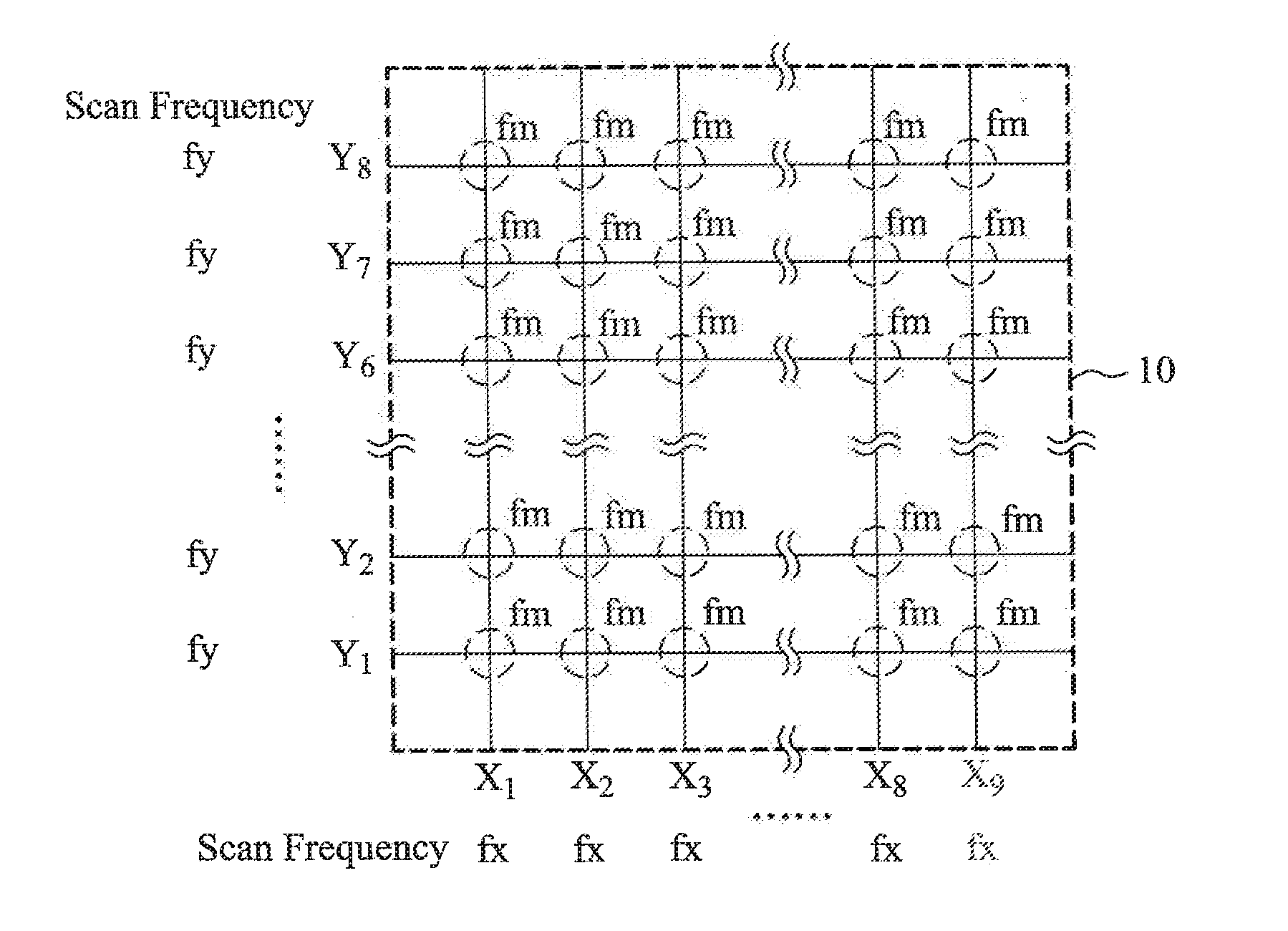
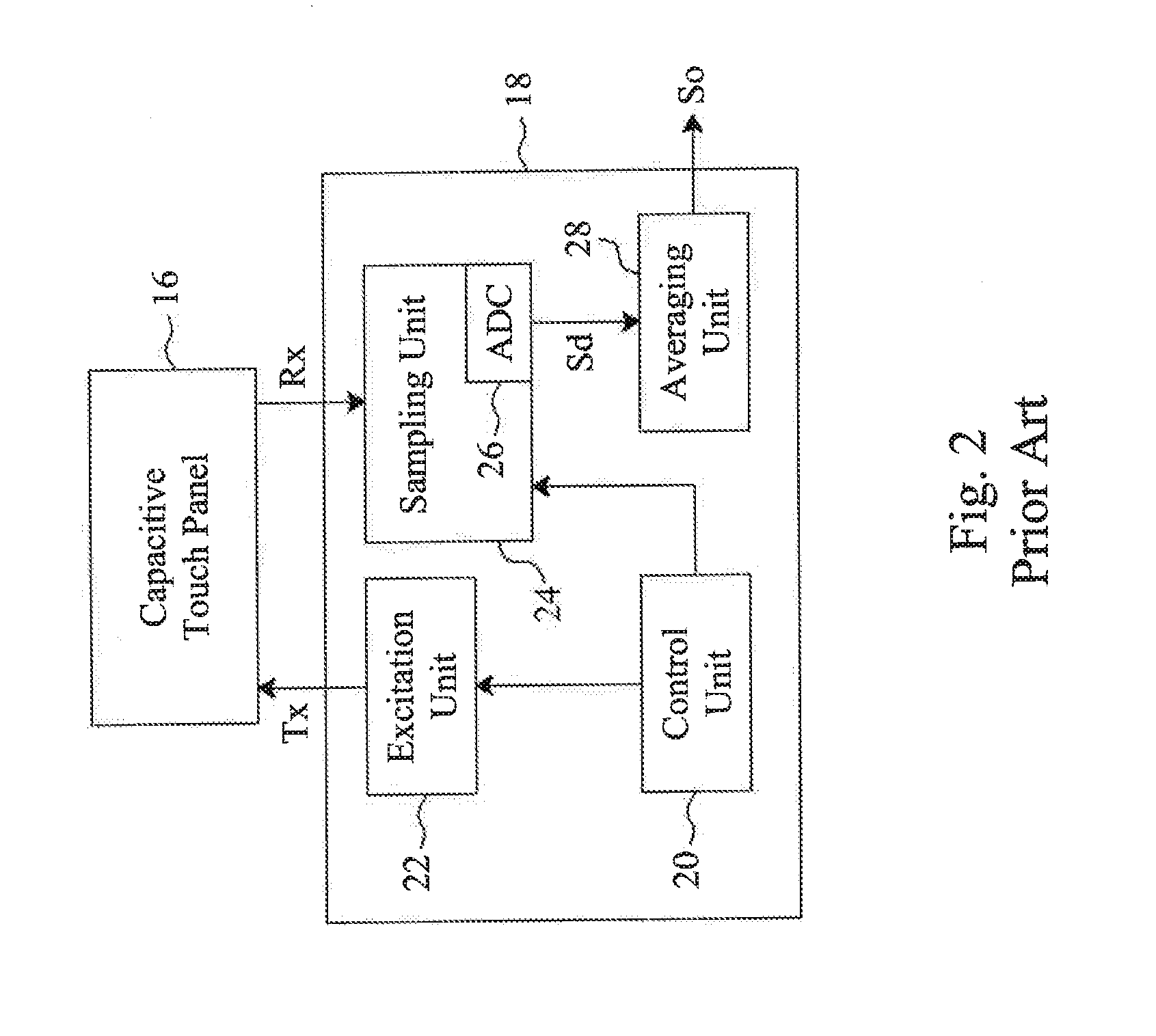
[0026]In the present invention, different scan frequencies are used to sense the traces in different directions. For example, referring to FIG. 4, in sensing a frame, a scan frequency fx is used to sense the self capacitances of X-direction traces X1-X9, and a scan frequency fy different from fx is used to sense the self capacitances of Y-direction traces Y1-Y8. To specify, the system uses the scan frequency fx to apply the excitation signal Tx to the X-direction traces X1-X9, and uses the same scan frequency fx to sample the sensed signal Rx fed back by the same X-direction traces X1-X9 and perform ADC conversion. The same is applied to the Y-direction trace Y1-Y8. The system uses another scan frequency fy to apply the excitation signal Tx to the Y-direction trace Y1-Y8, and uses the same scan frequency fy to sample the sensed signal Rx fed back by the same Y-direction trace Y1-Y8 and perform ADC conversion. Thereby, all the self capacitances in a frame can be obtained. Since diffe...

second embodiment

[0027]the present invention uses different scan frequencies to sense different traces in the same direction. For example, referring to FIG. 5, different scan frequencies fx1-fx9 are used to sense the self capacitances of the traces X1-X9, respectively, so noise of a certain frequency can interfere at most one trace. In an alternative embodiment, fewer scan frequencies may be used. For example, two scan frequencies fx1 and fx2 are used to sense the self capacitances of the traces X1-X4 and X5-X9, respectively, or two scan frequencies fx1 and fx2 are used to sense the self capacitances of the traces X1, X3, X5, X7, X9 and X2, X4, X6, X8, respectively.

[0028]By applying the sensing method of the embodiment depicted in FIG. 5 to a two-dimension touch sensor, as shown in FIG. 6, in sensing a frame, different scan frequencies are used to sense the self capacitances of the traces in the same direction and different scan frequencies are used to sense the mutual capacitances between the trace...

fourth embodiment

[0029]the present invention uses different scan frequencies to sense the self capacitance of a single trace or the mutual capacitance between two traces. For example, referring to FIG. 7, each trace is repeatedly sensed for N times for its self capacitance, and each time sensing uses a different scan frequency. Then the sensed values obtained by the different scan frequencies are averaged and taken as the sensed value of this trace, thereby further reducing the incidence of noise interference. Taking the trace X1 for example, the self capacitances of the trace X1 are repeatedly sensed for 32 times to see its variation. Among the 32 times of sensing, 32 different scan frequencies fx1,1-fx1,32 be used, respectively, or a scan frequency fx1,1 may be used for 16 times while another scan frequency fx1,2 may be used for the other 16 times, thereby preventing the sensed value of the 32 times of sensing for the trace X1 getting interference from noise of the same frequency. FIG. 8 illustrat...


PUM


Abstract

High noise immunity sensing methods and apparatus are provided for a capacitive touch device, which sense the capacitive touch device for self capacitance or mutual capacitance or both with different scan frequencies in a frame, to thereby suppress certain frequency noise interference. By combining time domain and space domain noise-eliminating approaches, probabilities of noise interference are reduced, without compromising other parameters.

Description

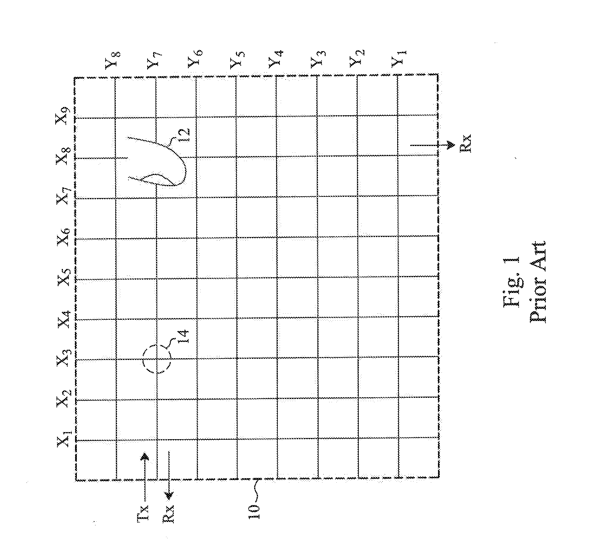
FIELD OF THE INVENTION[0001]The present invention is related generally to a capacitive touch device and, more particularly, to sensing methods and apparatus for a capacitive touch device.BACKGROUND OF THE INVENTION[0002]A capacitive touch device detects a touch point by sensing the capacitive variation of a capacitive touch sensor. For example, referring to FIG. 1, a two-dimension touch sensor 10 has X-direction traces X1-X9 and Y-direction traces Y1-Y8, wherein the traces X1-X9 and Y1-Y9 are not electrically connected to each other. In addition to having their self capacitances, the traces have mutual capacitances therebetween. When contacted by a finger 12, the trace has both of the self capacitance and the mutual capacitance it senses varying. Currently, a sensor structure for the capacitive touch device may use either all point scan or projection scan. The former one is measuring the variations of the mutual capacitances at all trace intersections during a sensing period of a fr...

Claims


Application Information

Patent Timeline
Patent Type & Authority Applications(United States)
IPC IPC(8): G06F3/044
CPCG06F3/0416G06F3/044G06F3/04166G06F3/0418G06F3/0446G09G5/18
Inventor WU, CHIA-MUHSU, YI-CHIAHUANG, JUNG-SHOUYANG, TUNG-MING
Owner ELAN MICROELECTRONICS CORPORATION
Learn More