High torque dental implant system

a dental implant and high-torque technology, applied in dental implants, dental surgery, medical science, etc., can solve the problems of high stress concentration, inability to resist implants, and inability to properly distribute the load of existing dental implants

Inactive Publication Date: 2013-10-03
UAB RES FOUND
View PDF18 Cites 21 Cited by
  • Summary
  • Abstract
  • Description
  • Claims
  • Application Information

AI Technical Summary

Problems solved by technology

However, due to improper thread pitch ratios and insufficient areas of contact between the implants and the jawbone of the subject, existing dental implants frequently fail to properly distribute these loads.
As a result, loading of existing dent

Method used


Image

  • High torque dental implant system
  • High torque dental implant system
  • High torque dental implant system

Examples


experimental examples

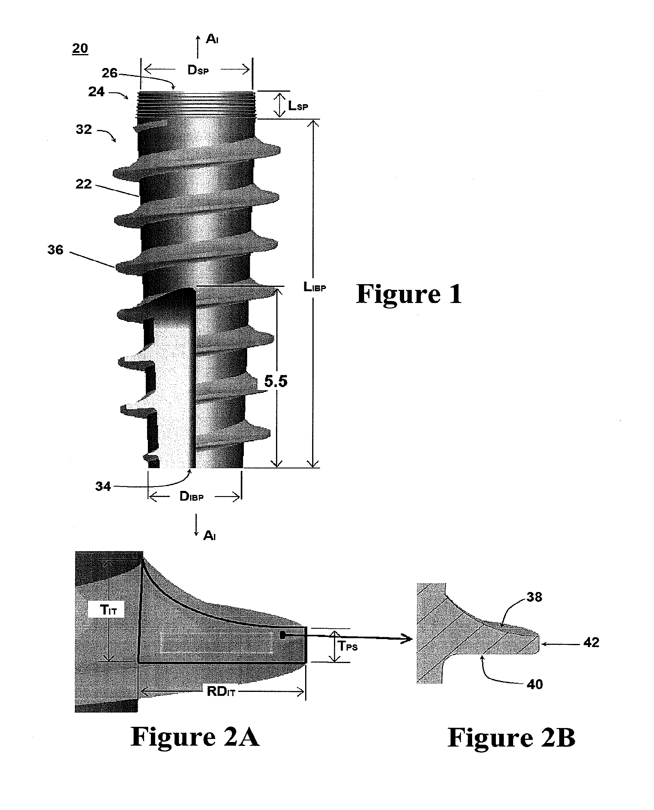
[0064]In one exemplary embodiment, as depicted in FIG. 4, the longitudinal length of the implant body portion can be constructed to be 10.0 mm. In this embodiment, the longitudinal length of the shoulder portion can be constructed to be 0.75 mm. As depicted, the diameter of the shoulder portion can be constructed to be 3.00 mm proximate the coronal end of the implant and 3.10 mm proximate the implant body portion. The diameter of the implant body portion tapers from 3.10 mm proximate the shoulder portion to 2.50 mm proximate the apical end of the implant. In this embodiment, the total surface area of the implant body portion, excluding the implant thread, was calculated to be 67.8490 mm2 (including all spaces between the implant thread) and 54.5066 mm2 (excluding one groove defined by the implant thread). The total surface area of the lower loading surfaces of the implant thread was calculated to be 47.0838 mm2, while the total surface area of the upper loading surfaces of the impla...


PUM


Abstract

A dental implant system for securing a dental prosthesis within a prepared site of a jawbone in a subject having an implant configured for insertion within the prepared site of the jawbone and an abutment configured for secure attachment to the implant. The implant can have a shoulder portion having a plurality of circumferential rings and a body portion that can be threaded. The implant can have an internal cavity that is configured or otherwise adapted to receive at least a portion of the abutment.

Description

CROSS-REFERENCE TO RELATED APPLICATION[0001]This application claims benefit of and priority to U.S. Provisional Patent Application Ser. No. 61 / 262,034, filed Nov. 17, 2009, which is incorporated by reference herein and made a part hereof.FIELD OF THE INVENTION[0002]This invention relates to a dental implant system for securing a dental prosthesis therein a prepared site of a jawbone in a subject. More specifically, this invention relates to a dental implant-abutment system having a novel thread profile and surface design.BACKGROUND OF THE INVENTION[0003]Known dental implants are designed to transfer biomechanical loads from the occlusal crown surface of the implant to the jawbone of a subject. However, due to improper thread pitch ratios and insufficient areas of contact between the implants and the jawbone of the subject, existing dental implants frequently fail to properly distribute these loads. As a result, loading of existing dental implants regularly leads to high stress conce...

Claims


Application Information

Patent Timeline
IPC IPC(8): A61C8/00
CPCA61C8/0006A61C8/0022A61C8/005A61C8/0066A61C8/0068A61C8/0078A61C8/0001A61C8/006A61C8/0069
Inventor REDDY, MICHAEL S.LEMONS, JACKGEURS, NICO C.O'NEAL, SANDRA JEANLIU, PERNG-RU
Owner UAB RES FOUND
Why Eureka
Try Eureka