Drug eluting folding balloon

a balloon and balloon technology, applied in balloon catheters, travelling articles, surgery, etc., can solve the problems of balloon catheters, patient prone to angina, heart muscle being deprived of oxygen,

Inactive Publication Date: 2013-10-03
OSCOR
View PDF4 Cites 34 Cited by
  • Summary
  • Abstract
  • Description
  • Claims
  • Application Information

AI Technical Summary

Benefits of technology

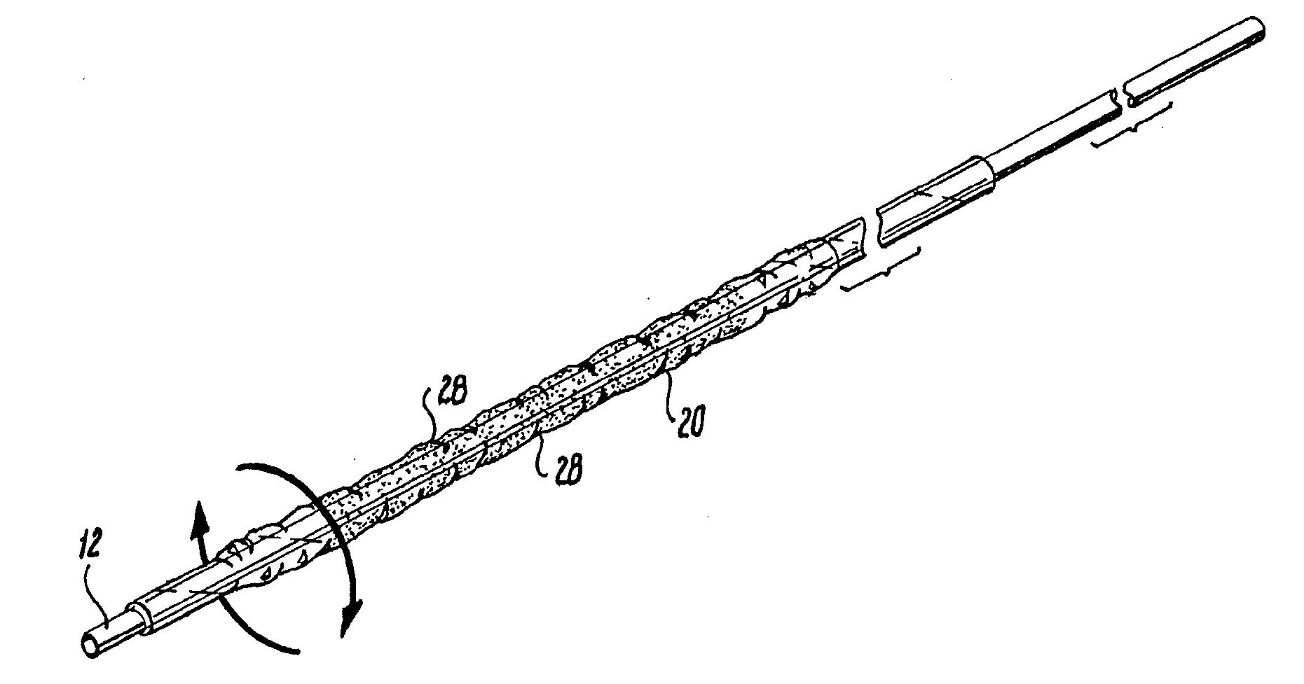
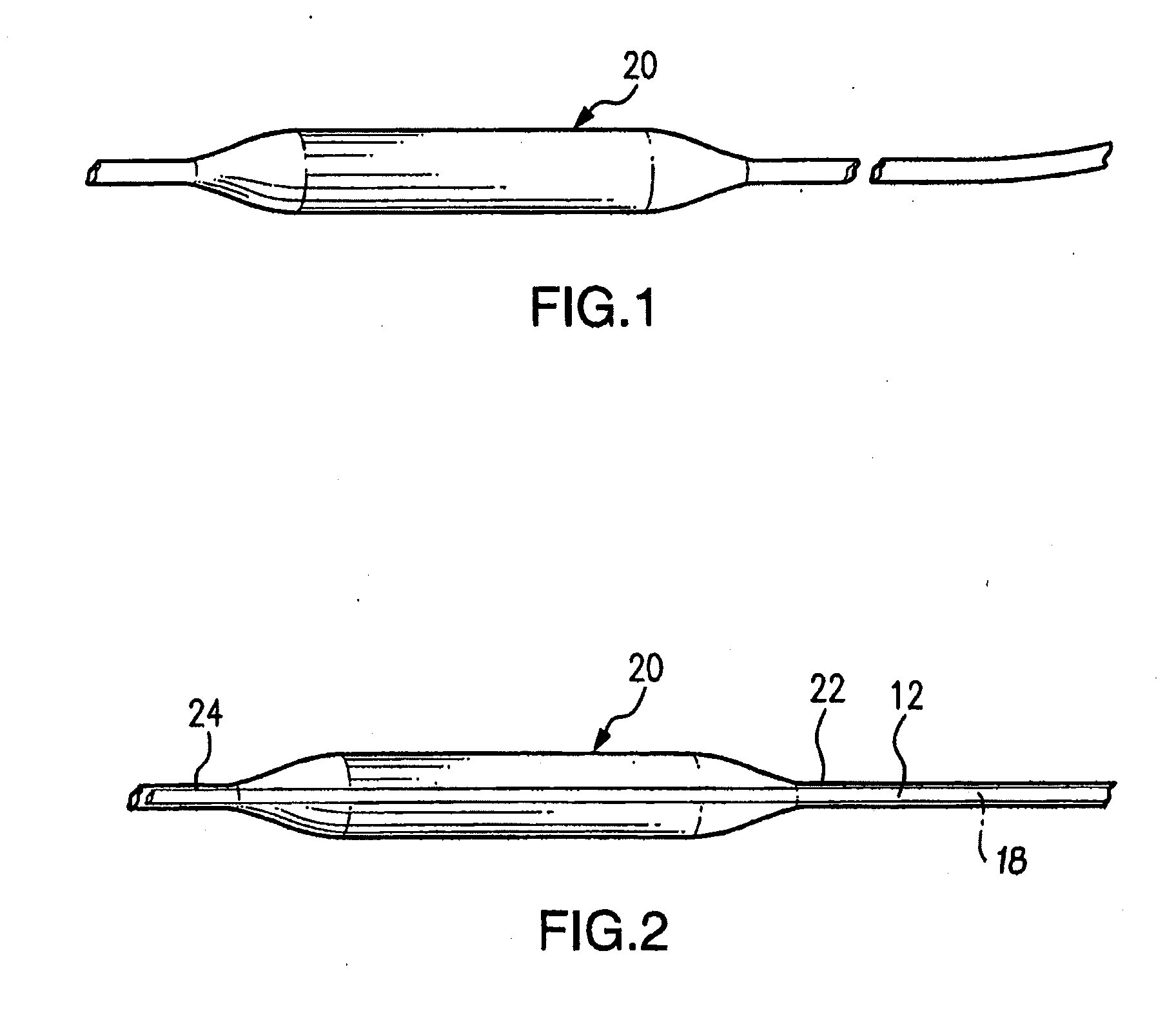
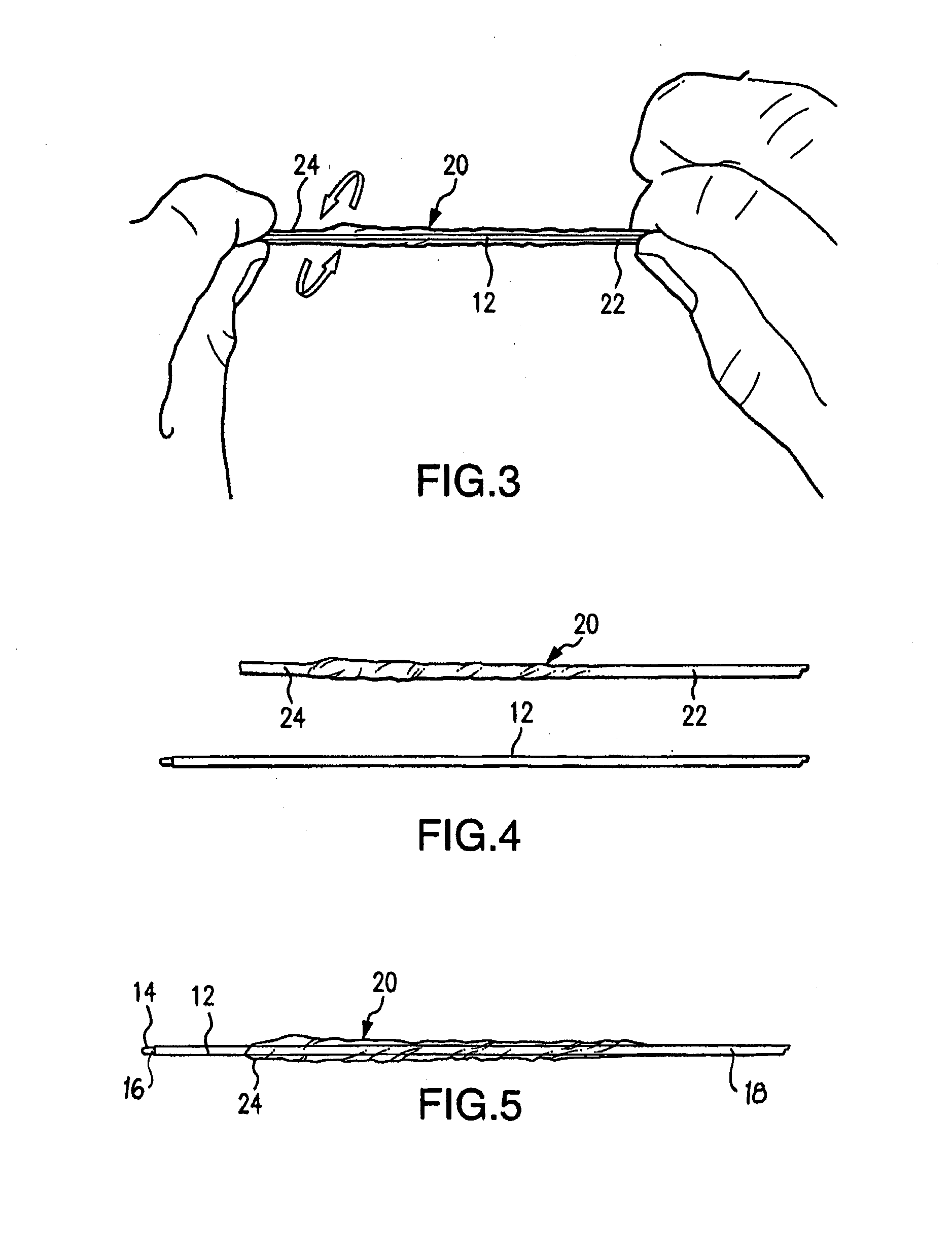
[0013]The proximal end portion of the inflatable balloon is affixed to the distal end portion of the first outer tubular member and the distal end portion of the inflatable balloon is affixed to the distal end portion of the second inner tubular member. The inflatable balloon resides on the first and second tubular members in a twisted turn orientation of a pre-determined angle relative to the proximal end portion of the inflatable balloon attached to the first outer tubular member. Folds caused by the twisted turn orientation are configured and adapted to protect the drug coating while the inflatable balloon is deflated, thereby reducing premature drug elution and increasing the reliability and consistency of drug delivery.
[0015]In another aspect, a tubular assembly consists of an inner tubular member configured for slideable reception within an outer tubular member, a balloon member, and a drug coating applied to at least a portion of the balloon member. A distal end portion of the inner tubular member extends distally from a distal end portion of the outer tubular member. Balloon member has first and second end regions wherein a first end region is attached to the distal end portion of the inner tubular member and the second end region is attached to the distal end portion of the outer tubular member. Balloon member is configured and adapted to fold when deflated and protect the drug coating therein reducing premature drug elution and increasing the reliability and consistency of drug delivery.
[0018]The tubular assembly consists of an inner tubular member configured for slideable reception within an outer tubular member such that a distal end portion of the inner tubular member extends distally from a distal end portion of the outer tubular member. A first end region of the balloon member is attached to the distal end portion of the inner tubular member and a second end region of the balloon member is attached to the distal end portion of the outer tubular member. Much as described above, the balloon member resides on the tubular assembly with a twisted turn orientation and at least a portion of the balloon member is coated with a drug. The tubular assembly is advanced such that the balloon member is exposed from the inner lumen of the introducer sheet. The inflating of balloon member exposes the drug and allows for delivery of the drug to the surgical site. The tubular assembly is retracted such that a substantial portion of the balloon member is located within the inner lumen of the introducer sheet.

Problems solved by technology

When blood flow is reduced in a coronary artery, the heart muscle becomes deprived of oxygen, and the patient is prone to suffer angina.
However, a noted problem associated with balloon catheters exists during the insertion and positioning of the balloon into the vessel.
If the drug coating gets prematurely eluted, diluted or absorbed during the insertion and positioning of the balloon, inconsistencies in treatment can occur.

Method used


Image

  • Drug eluting folding balloon
  • Drug eluting folding balloon
  • Drug eluting folding balloon

Examples


Embodiment Construction

[0039]The present invention is now described more fully with reference to the accompanying drawings, in which an illustrated embodiment of the present invention is shown. The present invention is not limited in any way to the illustrated embodiment as the illustrated embodiment described below is merely exemplary of the invention, which can be embodied in various forms, as appreciated by one skilled in the art. Therefore, it is to be understood that any structural and functional details disclosed herein are not to be interpreted as limiting, but merely as a basis for the claims and as a representative for teaching one skilled in the art to variously employ the present invention. Furthermore, the terms and phrases used herein are not intended to be limiting but rather to provide an understandable description of the invention.

[0040]It is to be appreciated and understood that the present invention, in accordance with the illustrated embodiments, is directed to a system and method for p...


PUM


Abstract

A balloon catheter includes a first outer tubular member, a second inner tubular member, an inflatable balloon, and a drug coating applied to at least a portion of the inflatable balloon. The inflatable balloon has opposing distal and proximal end portions. The inflatable balloon resides on the first and second tubular members in a twisted turn orientation of a pre-determined angle relative to the proximal end portion of the inflatable balloon attached to the first outer tubular member, such that the second inner tubular member achieves a constant torque of the balloon to twist and fold itself when retracted back into a portion of the first outer tubular member. Folds caused by the twisted turn orientation are configured and adapted to protect the drug coating while the inflatable balloon is deflated, thereby reducing premature drug elution and increasing the reliability and consistency of drug delivery.

Description

CROSS REFERENCE TO RELATED APPLICATIONS[0001]The present application is a continuation-in-part of co-pending U.S. application Ser. No. 13 / 343,228 filed Jan. 4, 2012, which is incorporated herein by reference in its entirety.BACKGROUND OF THE INVENTION[0002]1. Field of the Invention[0003]The present invention generally relates to balloon catheters, and more particularly to a drug eluting medical balloon catheter device and method for protecting a drug and delivering the drug to a surgical site using a balloon catheter that folds onto a catheter tube during balloon deflation, the folds protecting the drug, thereby reducing premature drug elution.[0004]2. Description of Related Art[0005]A balloon catheter generally comprises an inflatable balloon that is mounted along a distal end of an elongate catheter body (i.e., shaft). Balloon catheters are used by physicians in a wide variety of therapeutic procedures. In one common use, a folded balloon catheter is advanced through a blood vesse...

Claims


Application Information

Patent Timeline
Patent Type & Authority Applications(United States)
IPC IPC(8): A61M25/10A61F2/958
CPCA61M25/1002A61M25/1038A61M2025/105A61M25/10A61M25/104A61M2025/1004A45C5/03A45C9/00A45C2009/002A45F4/06
Inventor OSYPKA, THOMAS P.
Owner OSCOR
Why Eureka
Try Eureka