
Vascular device for valve leaflet apposition

a vascular device and valve leaflet technology, applied in the field of vascular devices, can solve the problems of inability to extend sufficiently radially inwardly, ulceration of venous stasis of skin and subcutaneous tissue, and great discomfort and pain for patients

Inactive Publication Date: 2006-05-09
REX MEDICAL LP
View PDF65 Cites 249 Cited by
  • Summary
  • Abstract
  • Description
  • Claims
  • Application Information

AI Technical Summary

Benefits of technology

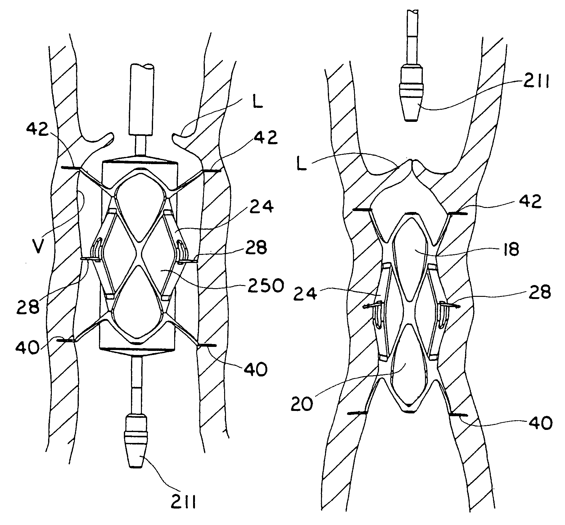
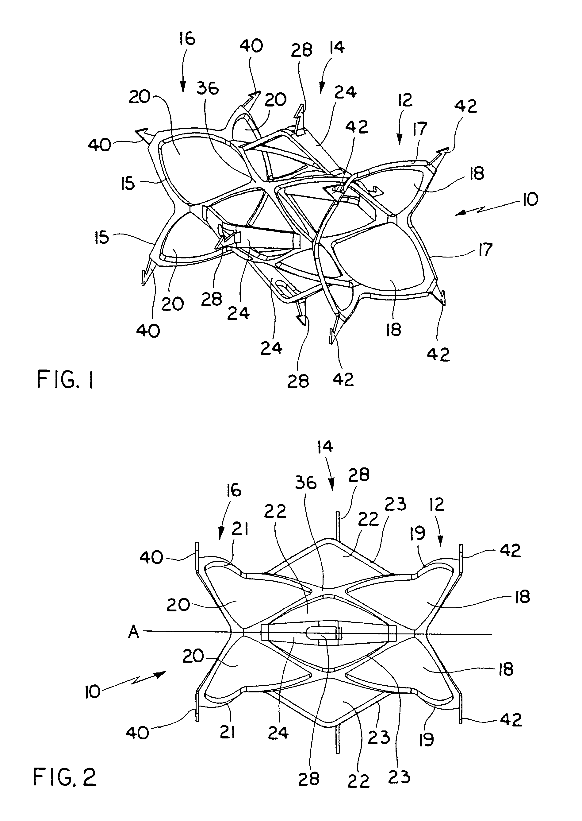
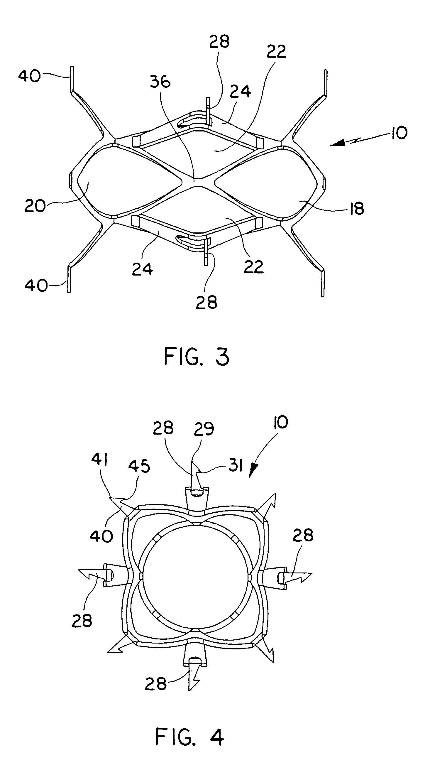
[0013]The vessel engaging members preferably extend from the distal and proximal portions of the device and have sharp ends to limit axial movement of the vessel wall and barbs to limit radial movement of the vessel wall to enhance retention (securement) of the vessel. The vessel engaging members preferably extend substantially parallel to a longitudinal axis of the device in the collapsed position and substantially perpendicular to the longitudinal axis in the extended position.
[0017]In another aspect of the present invention, a vascular device is provided comprising a tubular-like member expandable from a collapsed configuration to an expanded configuration. A plurality of vessel engaging members with penetrating tips extend from the proximal, distal and intermediate portions. Expansion of the member to the expanded configuration causes the distal and proximal portions to move axially inwardly and the intermediate portion to buckle radially outwardly to enable the vessel engaging members to securely engage the vessel wall.
[0024]reducing the diameter of the vascular device to move the vessel wall radially inwardly and bring the valve leaflets closer together.

Problems solved by technology

In the condition of venous valve insufficiency, the valve leaflets do not function properly as they thicken and lose flexibility, resulting in their inability to extend sufficiently radially inwardly to enable their tips to come into sufficient contact with each other to prevent retrograde blood flow.
Such retrograde blood flow, commonly referred to as reflux, leads to swelling and varicose veins, causing great discomfort and pain to the patient.
Such retrograde blood flow, if left untreated can also cause venous stasis ulcers of the skin and subcutaneous tissue.
Primary venous valve insufficiency is typically a condition from birth, where the vein is simply too large in relation to the leaflets so that the leaflets cannot come into adequate contact to prevent backflow.
Although sometimes successful, the tight stocking is quite uncomfortable, especially in warm weather, as the stocking must be constantly worn to keep the leaflets in apposition.
The elastic stocking also affects the patient's physical appearance, thereby potentially having an adverse psychological affect.
This physical and / or psychological discomfort sometimes results in the patient remove the stocking, thereby preventing adequate treatment.
This surgery requires a large incision, resulting in a long patient recovery time, scarring and carries the risks, e.g. anesthesia, inherent with surgery.
This procedure is complicated and has the same disadvantages of the major surgery described above.

Method used


Image

  • Vascular device for valve leaflet apposition
  • Vascular device for valve leaflet apposition
  • Vascular device for valve leaflet apposition

Examples


Embodiment Construction

[0073]Referring now in detail to the drawings where like reference numerals identify similar or like components throughout the several views, FIGS. 1–7 illustrate a first embodiment of the vascular device of the present invention and FIGS. 8–11 illustrate a second embodiment of the vascular device of the present invention. The devices, designated generally by reference numerals 10 and 100, are expanded to engage the internal wall of the vessel and contracted to pull the vessel walls radially inwardly. By pulling the vessel wall radially inwardly, the valve leaflets within the vessel are pulled closer together to a functional condition.

[0074]FIGS. 1–4 illustrate vascular device 10 of the first embodiment in the expanded configuration and FIGS. 5–7 illustrate vascular device 10 in the collapsed configuration. Vascular device 10 is preferably composed of a shape memory material, such as a nickel-titanium alloy commonly known as Nitinol, so that in its memorized configuration it assumes...


PUM


Abstract

A vascular system comprising a balloon catheter having an elongated shaft and an expandable balloon. A vascular device is mounted over the expandable balloon and composed of shape memory material and has a collapsed position and a memorized position. The vascular device is expandable to an expanded position, to engage the vessel walls and returnable substantially to the memorized position to bring the walls radially inwardly.

Description

[0001]This application is a divisional application of Ser. No. 09 / 877,639, filed Jun. 8, 2001, now U.S. Pat. No. 6,695,878, which claims priority from provisional application Ser. No. 60 / 214,120, filed Jun. 26, 2000, the entire contents of which is incorporated by reference.BACKGROUND[0002]1. Technical Field[0003]This application relates to a vascular device and more particularly to a vascular device for approximating vein valve leaflets for treating venous valve insufficiency.[0004]2. Background of Related Art[0005]Veins in the body transport blood to the heart and arteries carry blood away from the heart. The veins have one-way valve structures in the form of leaflets disposed annularly along the inside wall of the vein which open to permit blood flow toward the heart and close to prevent back flow. That is, when blood flows through the vein, the pressure forces the valve leaflets apart as they flex in the direction of blood flow and move towards the inside wall of the vessel, cre...

Claims


Application Information

Patent Timeline
Patent Type & Authority Patents(United States)
IPC IPC(8): A61F2/06A61B17/00A61B17/064A61B17/12A61F2/00A61F2/24A61F2/84A61F2/90
CPCA61B17/12109A61B17/12172A61F2/2475A61F2/2445A61B17/0644A61B17/12022A61B2017/00867A61F2220/0016A61F2/2442A61F2002/8483A61F2210/0019A61F2/2433
Inventor MCGUCKIN, JR., JAMES F.BRIGANTI, RICHARD T.
Owner REX MEDICAL LP
Learn More