Balloon catheter

a balloon and catheter technology, applied in the field of balloon catheters, can solve the problems of complex structures, no activity seems to have been directed toward the development of balloons, and no method or procedure for improving axial stability

Inactive Publication Date: 2000-01-04
BOSTON SCI SCIMED INC
View PDF4 Cites 237 Cited by
  • Summary
  • Abstract
  • Description
  • Claims
  • Application Information

AI Technical Summary

Problems solved by technology

However, no activities seem to have been directed toward the development of a balloon that incorporates both characteristics in a single device.
However, none describes any method or procedure for improving axial stability.
These structures complicate stent delivery systems and their use.

Method used


Image

  • Balloon catheter
  • Balloon catheter
  • Balloon catheter

Examples


Embodiment Construction

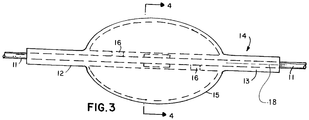
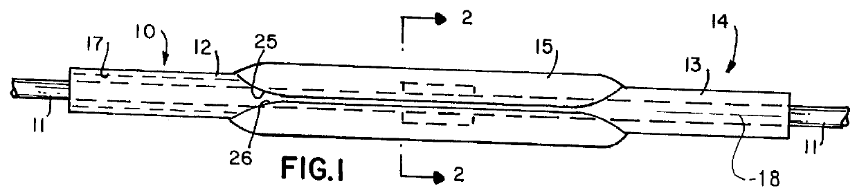
In the embodiment of FIGS. 1 through 4, a catheter 10 slides over a guidewire 11 and includes tubular portions 12 and 13 at a distal end 14 of the catheter 10. A balloon 15 lies longitudinally between and attaches to the tubular portions 12 and 13. Ports 16, shown in phantom in FIG. 3, allow fluid to be admitted to the area of the balloon 15 for expansion. The fluid is supplied either through a lumen 17, in FIG. 1 that carries the guidewire 11 or through an auxiliary lumen (not shown), all is well known in the art.

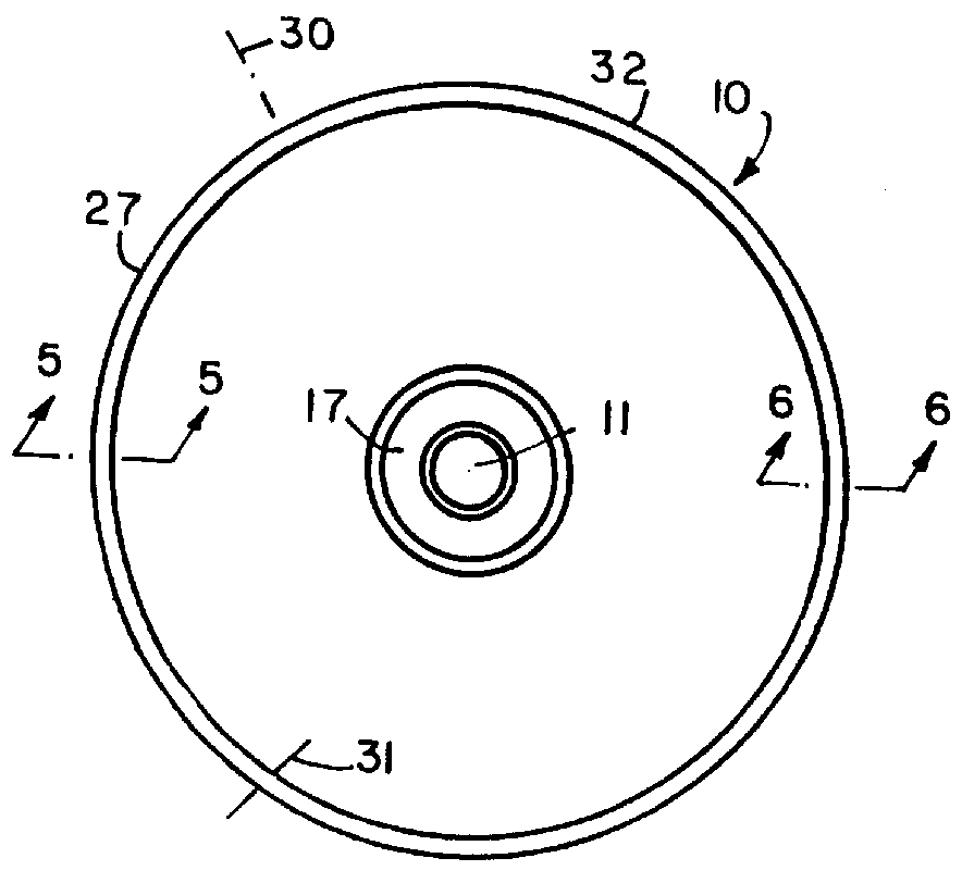
FIGS. 1 and 2 depict the disposition of thin balloon material about the catheter 10 and an axis 18 in a compact position. For clarity, FIG. 2 depicts the material out of scale in spaced adjacent layers. In an actual balloon the 5 layers would be tightly packed. The balloon 15 is formed in three concentric layers including an inside layer 20, and intermediate layer 21 and an outer layer 22. The intermediate layer 21 folds back over the inside layer 22 such that the folds 23...


PUM

PropertyMeasurementUnit
coefficients of sliding frictionaaaaaaaaaa
coefficient of sliding frictionaaaaaaaaaa
sliding frictionaaaaaaaaaa

Abstract

An expansible balloon catheter has at least a first exterior surface with a given coefficient of friction and a second exterior surface with a greater coefficient of friction. In a compact form only the first exterior surface is exposed to produce one coefficient of friction during transfer of the collapsed or uninflated balloon to and across a lesion. When inflated, the second surface dominates the first surface and produces a second coefficient of friction.

Description

1. Field of the InventionThis invention generally relates to balloon catheters and more particularly to the structure of and method of manufacture of balloon catheters.2. Description of Related ArtCoronary balloon angioplasty involves the steps of inserting a deflated balloon into a coronary artery, advancing the balloon across a lesion until the balloon is centered at the lesion and then inflating the balloon to dilate and remove the stenosis. Significant efforts have been directed toward constructing balloons with smaller cross sections so that they can better cross a tight lesion. However, experience with these smaller balloon catheters has highlighted two desirable, but until now antithetical, characteristics. First, the balloon should exhibit very low coefficient of sliding friction to facilitate initial positioning with minimal trauma. Secondly the balloon should exhibit longitudinal or axial stability during and after inflation. This stability is needed to overcome any tenden...

Claims


Application Information

Patent Timeline
Patent Type & Authority Patents(United States)
IPC IPC(8): A61F2/06A61M25/10A61M25/00A61M29/02A61F2/84
CPCA61F2/958A61M25/1002A61M25/1027A61M25/1038A61M25/104A61M25/0043A61M25/1029A61M2025/0047A61M2025/1004A61M2025/1031A61M2025/1086A61M2025/1088
Inventor ABELE, JOHN E.SAHATJIAN, RONALD A.
Owner BOSTON SCI SCIMED INC
Why Eureka
Try Eureka