Stiffened balloon catheter for dilatation and stenting

a balloon catheter and dilatation technology, which is applied in the field of balloon catheters for angioplasty and the delivery of stents and stentgrafts, can solve the problems of inadequate dilatation of stenotic, the length of the stent, and the failure of the stent to produce a uniform diameter, so as to improve the stiffness of the stiffening member, and improve the stiffness

Inactive Publication Date: 2005-09-13
GRAYZEL JEFFREY +1
View PDF38 Cites 258 Cited by
  • Summary
  • Abstract
  • Description
  • Claims
  • Application Information

AI Technical Summary

Benefits of technology

[0014]The balloon catheter of the present invention comprises a catheter having a flow passage for pressurized fluid with an expandable chamber, such as a balloon, connected in-between distal and proximal catheter sections. The expandable chamber is generally bounded by a wall suitably configured for containing a pressurized fluid. A plurality of stiffening members are peripherally disposed along the expandable chamber. Such stiffening members may be embedded in the wall or connected to the inner or outer surface of the wall. The stiffening members generally move with the wall of the expandable chamber and are configured to resist localized deformation in the wall of the expandable chamber.
[0023]It is another object of the invention to provide improved stiffening members for balloons to engage a lumen and to engage and fracture occlusive material within a lumen.
[0024]It is a further object of the invention to provide improved stiffening members for balloons to retain a stent or stent-graft for delivery to or repositioning at a target site in a lumen and for reconfiguring a partially deployed stent or stent-graft.

Problems solved by technology

Unfortunately, currently available balloon systems for angioplasty and for delivery and expansion of stents often fail to properly deploy the stent to produce a uniform diameter and cross-sectional area along the length of the stent.
If the stent adopts a “waist configuration”, it is generally indicative of inadequate dilatation of the stenotic lesion within the blood vessel.
However, the more rigid material still has an elastic limit.
Balloons made of such material and excessively inflated will be permanently deformed, and may eventually burst.
Such deformed balloons are much more difficult to remove from the patient.
Moreover, increasing the pressure in the balloon increases the potential for rupture and serious harm to the patient.
Even the use of higher pressures permitted by more rigid balloons are insufficient to dilate some arterial stenoses, particularly if they have an annular configuration.
Some residual stenoses and a non-uniform cross-sectional area along the length of the stent will result.
Another problem frequently encountered during balloon dilation of stents is the occurrence of flaring of the stent at its ends.
The resulting different diameters of expansion are transferred to the stent causing a “trumpet-like” outward flaring of the stent at its ends, which is undesirable.
Additionally, there are several problems with the conventional methodology for delivering a stent to an occlusive site with a conventional balloon catheter.
As the operator tries to advance or withdraw the catheter, the calcified matter or other irregularity may catch hold of the stent and capture it in place while the catheter is moved, causing the stent to separate from the balloon.
If the stent is displaced with respect to the balloon, slips partially off the balloon, or separates from the balloon entirely, then the stent will not deploy properly.
If the undeployed stent separates from the balloon entirely, retrieving the undeployed stent becomes a very serious problem.
Similarly, a stent that is only partially deployed or is incorrectly positioned presents a very significant risk to the patient.
Where an occlusive site is only partially accessible by means of a conventional balloon catheter, i.e., only one end of an occlusion has an inner diameter that is of sufficient size to receive a balloon catheter, expansion of the balloon often causes the entire device to be squeezed and slip out of the occlusive site entirely.
Thus, attempts to open such partially accessible occlusive sites often fail.
Such force causes additional stress at the occlusive site and in surrounding structures which present a further risk of rupturing the target site or causing damage to the surrounding areas.
The same difficulties are encountered in attempting to position and deploy a stent-graft with a conventional balloon catheter.
Incomplete stent-graft deployment can result in troublesome endoleaks caused by inadequate or otherwise ineffective sealing of the stent-graft at the ends with the interior of the vessel.
Such endoleaks allow a channel of blood flow to develop that bypasses the stent-graft, greatly reducing its effectiveness and potentially causing the stent-graft to migrate.
Where stent-grafts are deployed to exclude aneurysms, such as in the endovascular repair of an abdominal aortic aneurysm, endoleaks are a very significant problem in that they may allow flow to an aneurysm that could cause the aneurysm to rupture.
Additionally, it has also been found that an inherent limitation of the balloon catheter device described in U.S. Pat. No. 4,796,629 is its limited maneuverability for deployment in the vascular system.
The stiffeners of such a device are fairly rigid, have a fixed length in excess of the turning radius needed to navigate certain pathways and have a fixed, although not necessarily uniform, cross-section.
As a result, it can be particularly difficult to navigate the device of U.S. Pat. No. 4,796,629 through the vascular system to reach certain occlusions in smaller vessels without utilizing non-standard entry locations or invasive manual procedures for straightening tortuous vascular pathways.

Method used


Image

  • Stiffened balloon catheter for dilatation and stenting
  • Stiffened balloon catheter for dilatation and stenting
  • Stiffened balloon catheter for dilatation and stenting

Examples


Embodiment Construction

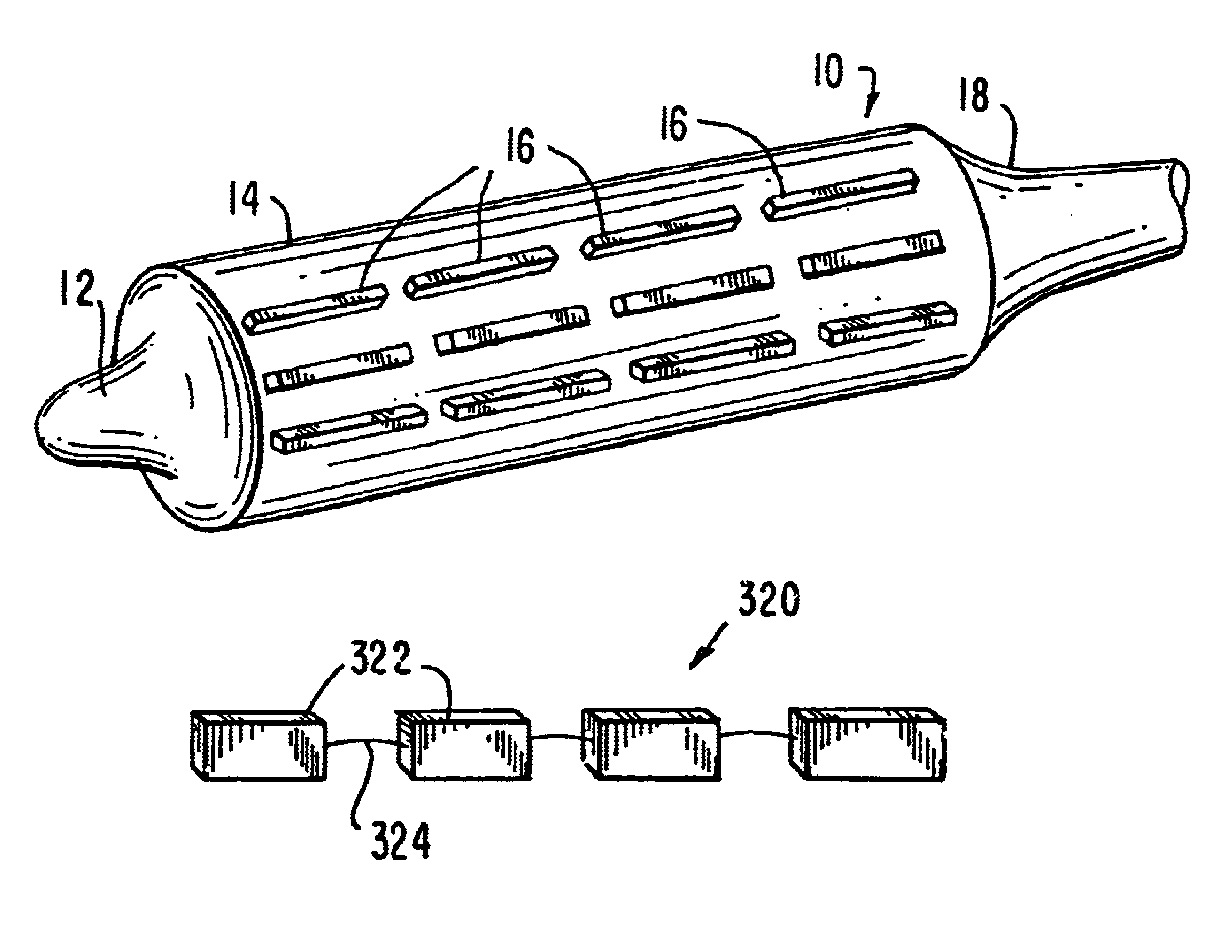
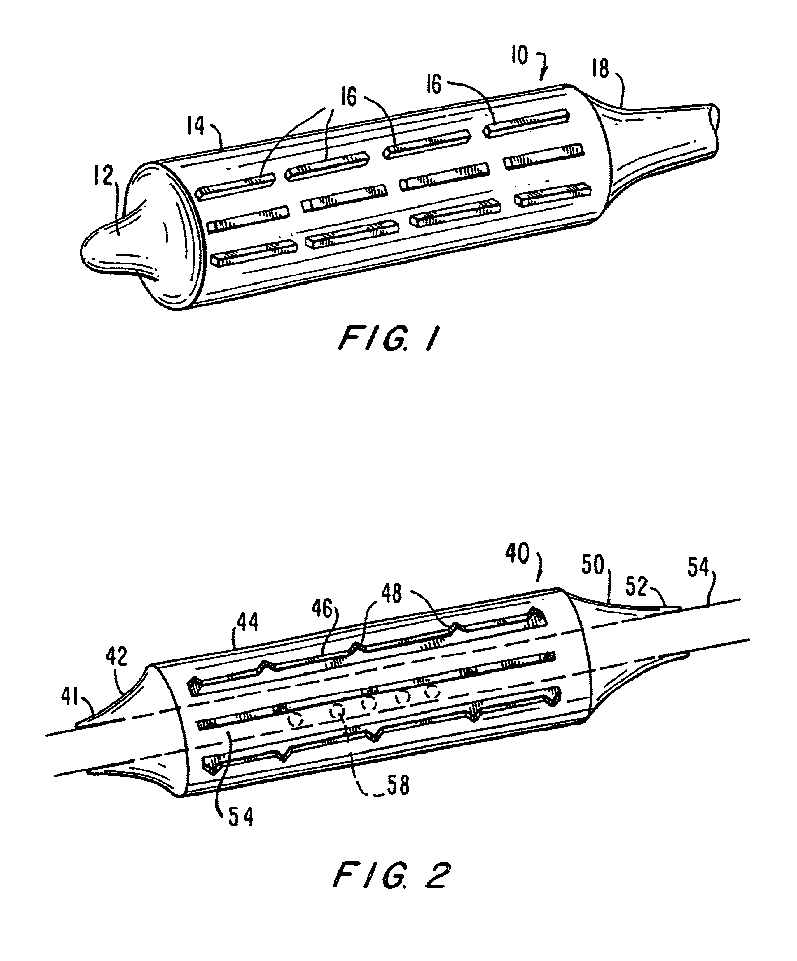
[0044]FIG. 1 is a drawing of an embodiment of the present invention, indicated generally as device 10, particularly suited for navigating curved or otherwise angled passages. In angio-valvuloplasty procedures, device 10 may be advantageously utilized to access vessels via passages that have curved sections and, in certain embodiments, even passages that include acute angles. Device 10 comprises a balloon having a distal end 12, a balloon 14, discontinuous stiffening members 16 and proximal end 18. Device 10 is generally comprised of standard inert balloon catheter materials suitable for introduction into the human body.

[0045]Distal end 12, balloon 14 and proximal end 18 are preferably comprised of a thin, flexible, and generally inelastic material that expands outwardly to assume a predetermined shape at a particular interior pressure, e.g., an envelope with a fixed configuration. Alternatively, end 12, balloon 14 and end 18 are formed from an elastic material. While end 12, balloon...


PUM


Abstract

The present invention pertains to a stiffened balloon which can be used in angioplasty, endovascular, and valvuloplasty procedures or as a delivery balloon to deliver a stent or a stent-graft. Longitudinally discontinuous stiffening members connected to the expandable balloon stiffen the balloon but allow it to be navigated through curved passages. Projections on the stiffening members may engage, incise, crush, fracture, or pierce occlusions or retain a stent or stent-graft. Radio-opaque portions may be referenced to determine orientation. Longitudinally continuous stiffening members bearing projections and connected to the balloon perform in a similar manner.

Description

[0001]This application claims the benefit of U.S. Provisional Application No. 60 / 220,297, filed Jul. 24, 2000.FIELD OF THE INVENTION[0002]The invention relates to the field of balloon catheters for angioplasty and the delivery of stents and stent-grafts.BACKGROUND OF THE INVENTION[0003]Inflatable balloons are employed to dilate stenotic arteries in angioplasty, i.e., percutaneous transluminal coronary angioplasty (PTCA), to dilate stenotic cardiac valves in valvuloplasty, and to deliver and reconfigure stents and stent-grafts. To prevent late lumen loss and restenosis, a stent is carried on a balloon, positioned and expanded to remain in a dilated vessel. Unfortunately, currently available balloon systems for angioplasty and for delivery and expansion of stents often fail to properly deploy the stent to produce a uniform diameter and cross-sectional area along the length of the stent. This results from the very nature of such a cylindrical balloon which is made of a thin, flexible m...

Claims


Application Information

Patent Timeline
Patent Type & Authority Patents(United States)
IPC IPC(8): A61F2/06A61M29/02A61F2/84A61M25/00A61M25/10
CPCA61F2/958A61M25/104A61B17/320725A61B2017/22061A61F2002/9583A61M2025/1079A61M2025/1084A61M2025/1086A61M2025/109
Inventor GRAYZEL, JEFFREYGRAYZEL, JOSEPH
Owner GRAYZEL JEFFREY
Why Eureka
Try Eureka