
Integrated distribution system optimization

a distribution system and integrated technology, applied in the direction of electric variable regulation, process and machine control, instruments, etc., can solve the problems of power quality problems, electricity price spikes, and electricity shortages,

Active Publication Date: 2013-10-03
GENERAL ELECTRIC CO
View PDF5 Cites 65 Cited by
  • Summary
  • Abstract
  • Description
  • Claims
  • Application Information

AI Technical Summary

Benefits of technology

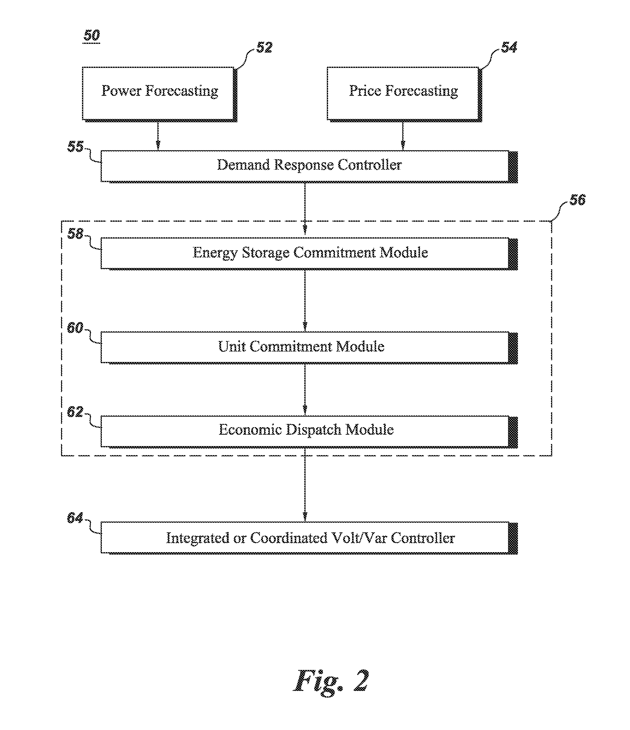
The present invention provides a system and method for predicting and controlling electrical power in a distribution system. The system includes a power forecasting module, a demand response module, an energy storage commitment module, and an integrated Volt-VAR control module. The power forecasting module predicts the load and power generation profiles for the distribution system for a period of interest. The energy storage commitment module determines a charging and discharging schedule for energy storage devices in the distribution system based on the load profile and the power generation profile. The demand response module estimates the available demand response on the distribution system based on the load profile and the power generation profile, and optimizes the load profile by dispatching an optimal demand response. The integrated Volt-VAR control module controls distribution assets to maintain a voltage profile for the period of interest based on the economic dispatch module and the controlled distribution assets. The technical effects include improved accuracy in predicting and controlling power demand and supply, increased flexibility in managing renewable energy sources, and improved reliability and stability of the distribution system.

Problems solved by technology

Increased demands on electrical power systems have resulted in incidences of electricity shortages, power quality problems, rolling blackouts, and electricity price spikes.

Method used


Image

  • Integrated distribution system optimization
  • Integrated distribution system optimization
  • Integrated distribution system optimization

Examples


Embodiment Construction

[0016]As used herein, the terms “controller” or “module” refers to software, hardware, or firmware, or any combination of these, or any system, process, or functionality that performs or facilitates the processes described herein.

[0017]When introducing elements of various embodiments of the present invention, the articles “a,”“an,”“the,” and “said” are intended to mean that there are one or more of the elements. The terms “comprising,”“including,” and “having” are intended to be inclusive and mean that there may be additional elements other than the listed elements.

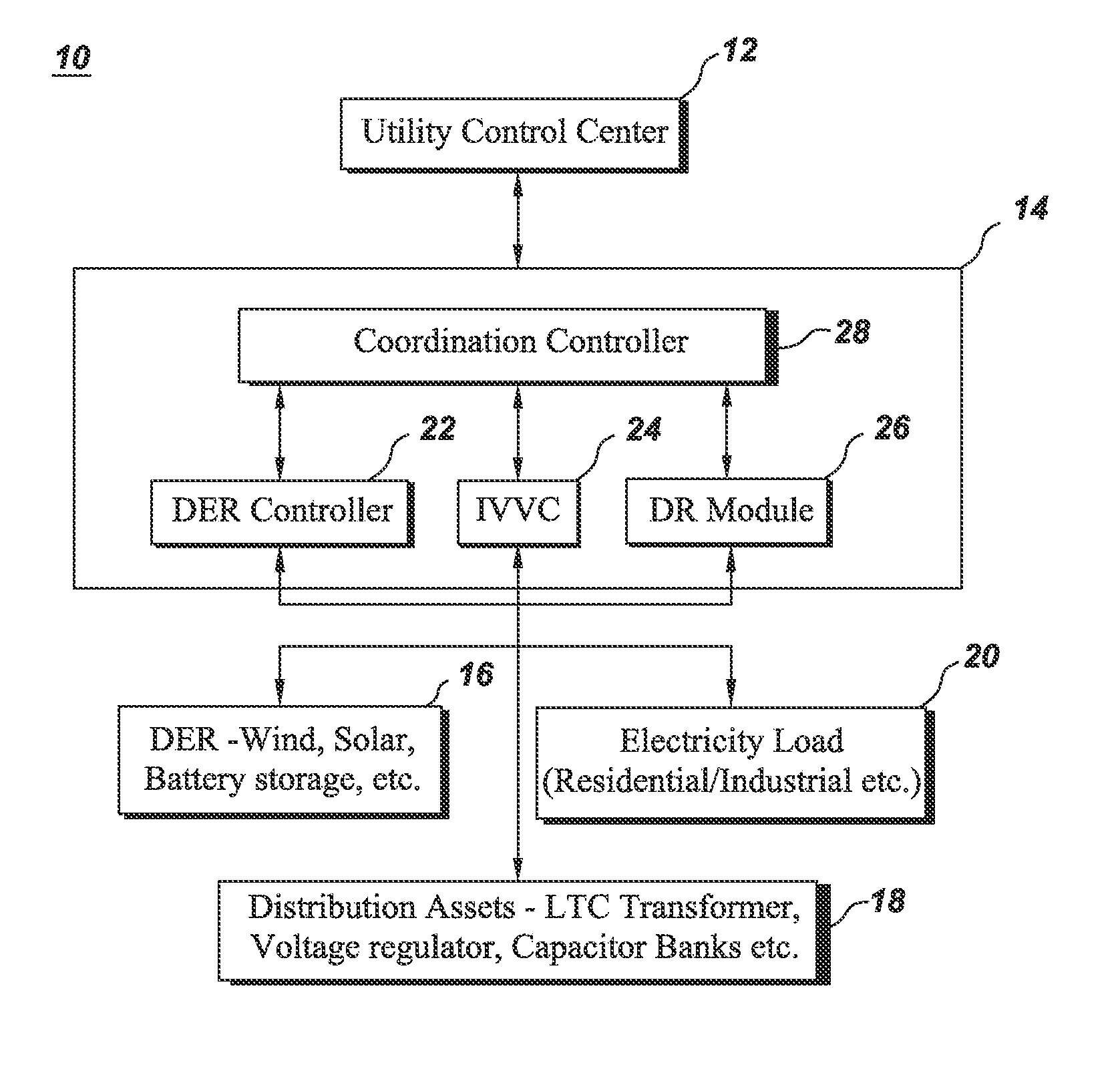
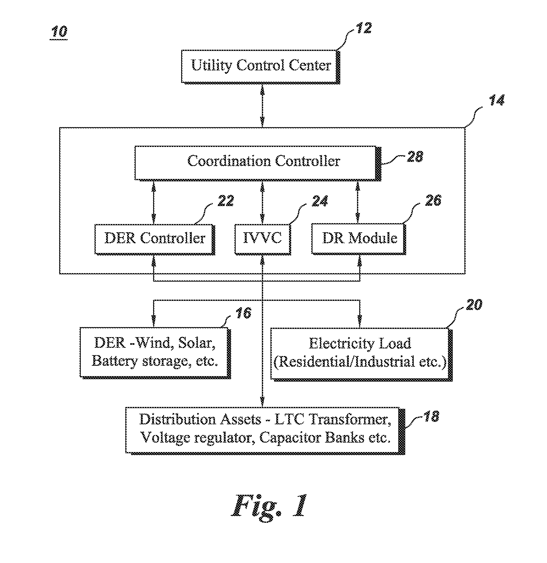
[0018]FIG. 1 shows a part of a power system network 10 in accordance with an embodiment of the present invention. Power system network 10 includes a utility control center 12, distribution management system 14, DERs 16, distribution assets 18 and electricity loads 20. Electricity loads 20 may include residential, commercial or industrial loads and receive power from either DERs 16 or other parts of a power grid (not shown...


PUM


Abstract

A power forecasting module determines a load forecast of a distribution system (DS) and a power generation forecast of distributed energy resources (DERs). A demand response (DR) module estimates an available DR based on the load and the power generation forecast and modifies the load forecast by dispatching an optimal DR. An energy storage commitment module determines a charging / discharging schedule of energy storage devices in the system based on the modified load profile and generates a second load profile by incorporating the charging / discharging schedule of energy storage devices. An unit commitment (UC) module determines a DER schedule of supplying electrical power to the loads in the second load profile based on a first objective function. An economic dispatch (ED) module determines an optimum operating point for each DER and an Integrated Volt-VAR Control (IVVC) module controls distribution assets to maintain a voltage profile in the system.

Description

BACKGROUND[0001]The invention relates generally to an electric power system and more specifically to control of electric power in the electric power system.[0002]The basic structure of the electric power system comprises various hardware elements such as generators, transformers, and real-time monitoring equipment, and software such as power flow analysis software, fault detection software, and restoration software for generation, transmission, and distribution of electricity.[0003]Traditionally, electricity is transmitted from large centralized power plants to the load centers through long transmission lines. Increased demands on electrical power systems have resulted in incidences of electricity shortages, power quality problems, rolling blackouts, and electricity price spikes. Distributed Energy Resources (DERs) which are small-scale power generation sources located close to where electricity is used (e.g., a home or business), provide an alternative to or an enhancement of the t...

Claims


Application Information

Patent Timeline
Patent Type & Authority Applications(United States)
IPC IPC(8): G05F5/00
CPCG05F5/00Y04S20/222Y02B70/3225H02J3/14H02J3/381H02J3/16H02J3/28H02J3/003H02J2203/20Y02E40/30Y02E40/70Y02E60/00Y04S10/50Y04S40/20
Inventor KROK, MICHAEL JOSEPHBLACK, JASON WAYNEGENC, SAHIKAVENKATA SATYA, MURALI MOHAN BAGGU DATATYAGI, RAJESH
Owner GENERAL ELECTRIC CO
Learn More